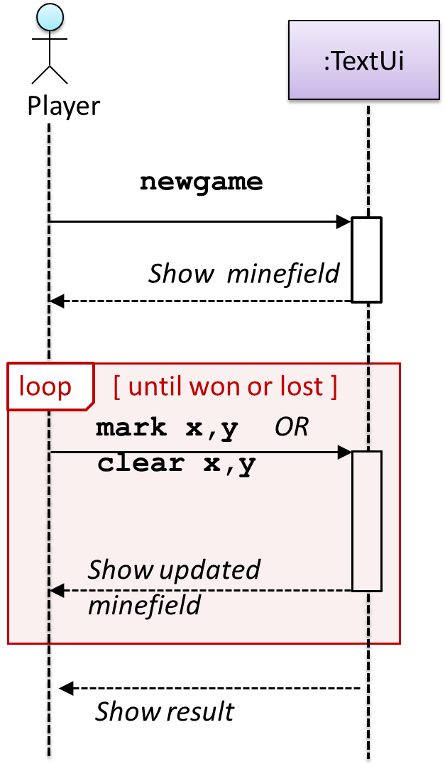
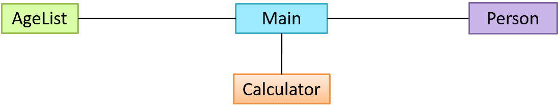
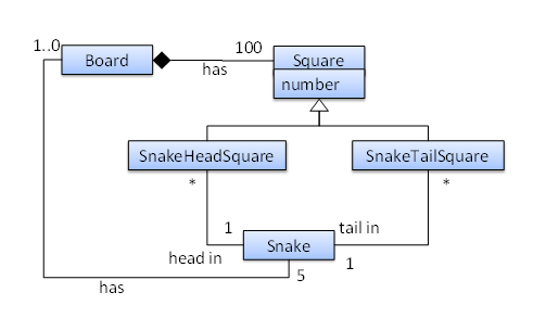
Continuing with the example in [
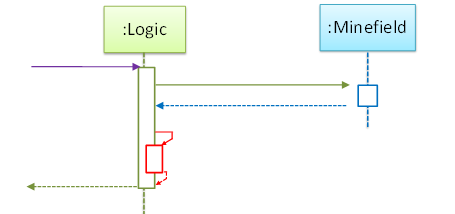
Design → Modeling → Modeling a Solution → Basic], next let us model how the TextUi interacts with the Logic to support the mark or clear operations until the game is won or lost.
Design → Modeling → Modeling a Solution →
Basic
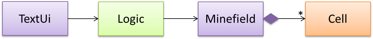
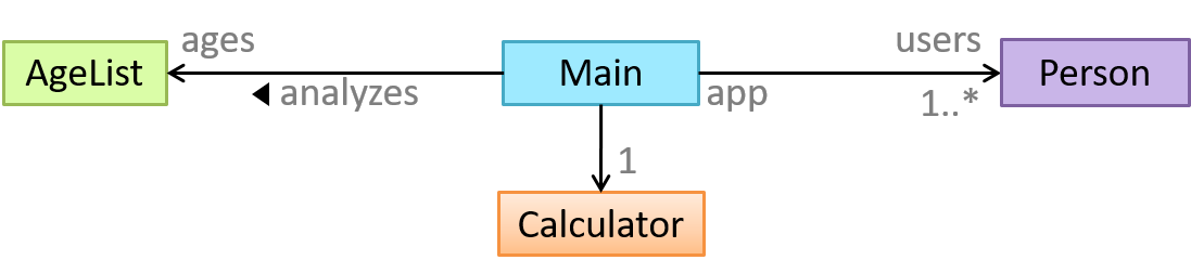
As mentioned in [
Design → Modeling → Modeling a Solutions → Introduction], this is the Minesweeper design you have come up with so far. Our objective is to analyze, evaluate, and refine that design.
Design → Modeling → Modeling a Solution →
Introduction
You can use models to analyze and design a software before you start coding.
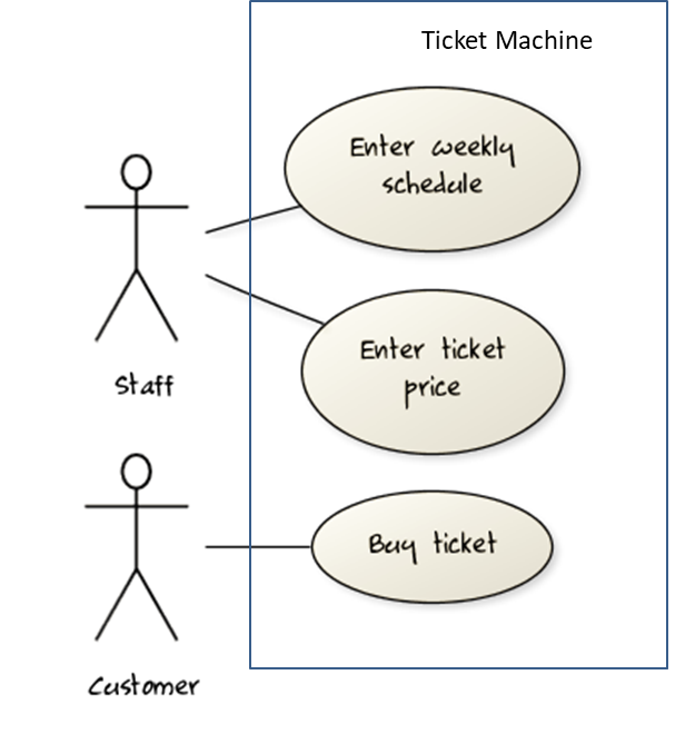
Suppose You are planning to implement a simple minesweeper game that has a text based UI and a GUI. Given below is a possible OOP design for the game.
Before jumping into coding, you may want to find out things such as,
- Is this class structure is able to produce the behavior we want?
- What API should each class have?
- Do we need more classes?
To answer those questions, you can analyze the how the objects of these classes will interact with each other to produce the behavior you want.
Let us start by modelling a sample interaction between the person playing the game and the TextUi object.
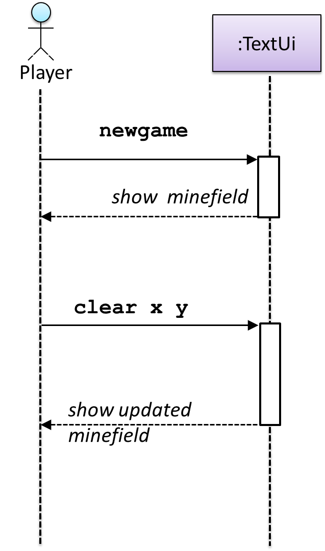
newgame and clear x y represent commands typed by the Player on the TextUi.
How does the TextUi object carry out the requests it has received from player? It would need to interact with other objects of the system. Because the Logic class is the one that controls the game logic,
the TextUi needs to collaborate with Logic to fulfill the newgame request. Let us extend the model to capture that interaction.
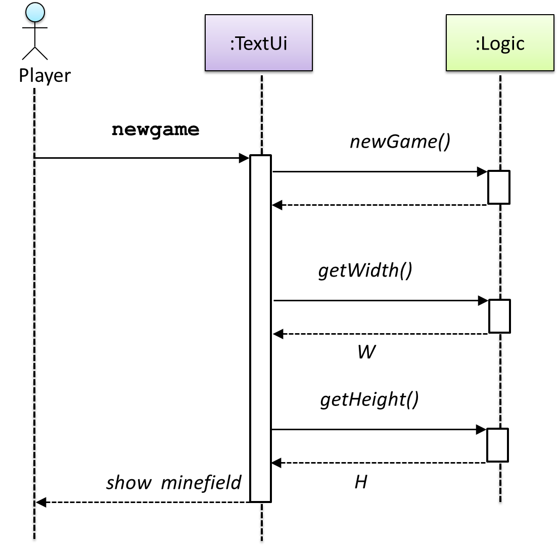
W = Width of the minefield; H = Height of the minefield
The above diagram assumes that W and H are the only information TextUi requires to display the minefield to the Player. Note that there could be other ways of doing this.
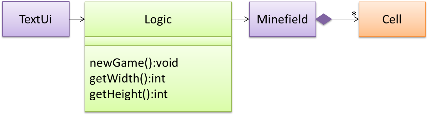
The Logic methods we conceptualized in our modelling so far are:
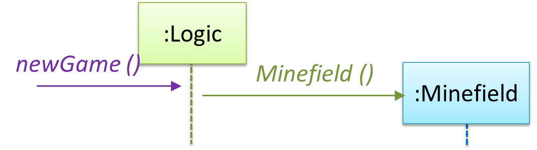
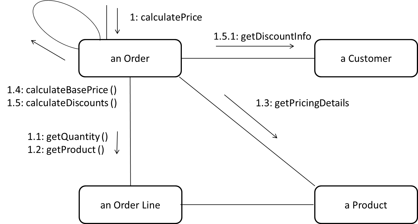
Now, let us look at what other objects and interactions are needed to support the newGame() operation. It is likely that a new Minefield object is created when the newGame() method is called.
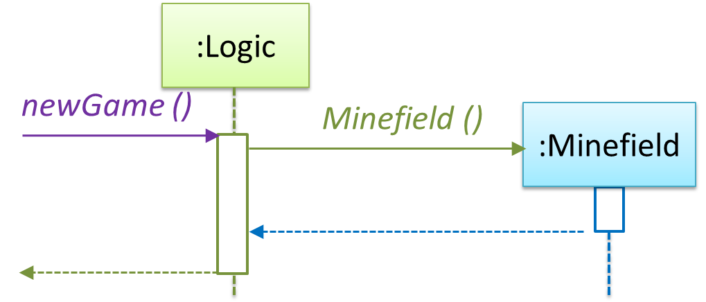
Note that the behavior of the Minefield constructor has been abstracted away. It can be designed at a later stage.
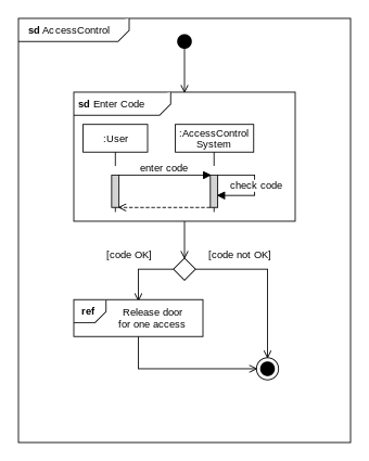
Given below are the interactions between the player and the Text UI for the whole game.
💡 Note that
a similar technique can be used when discovering/defining the architecture-level APIs.
Defining the architecture-level APIs for a small Tic-Tac-Toe game:
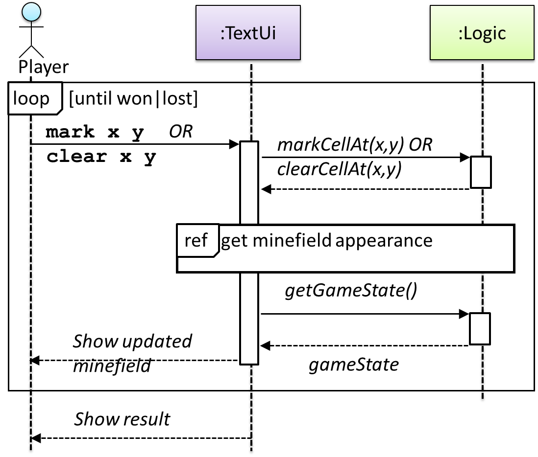
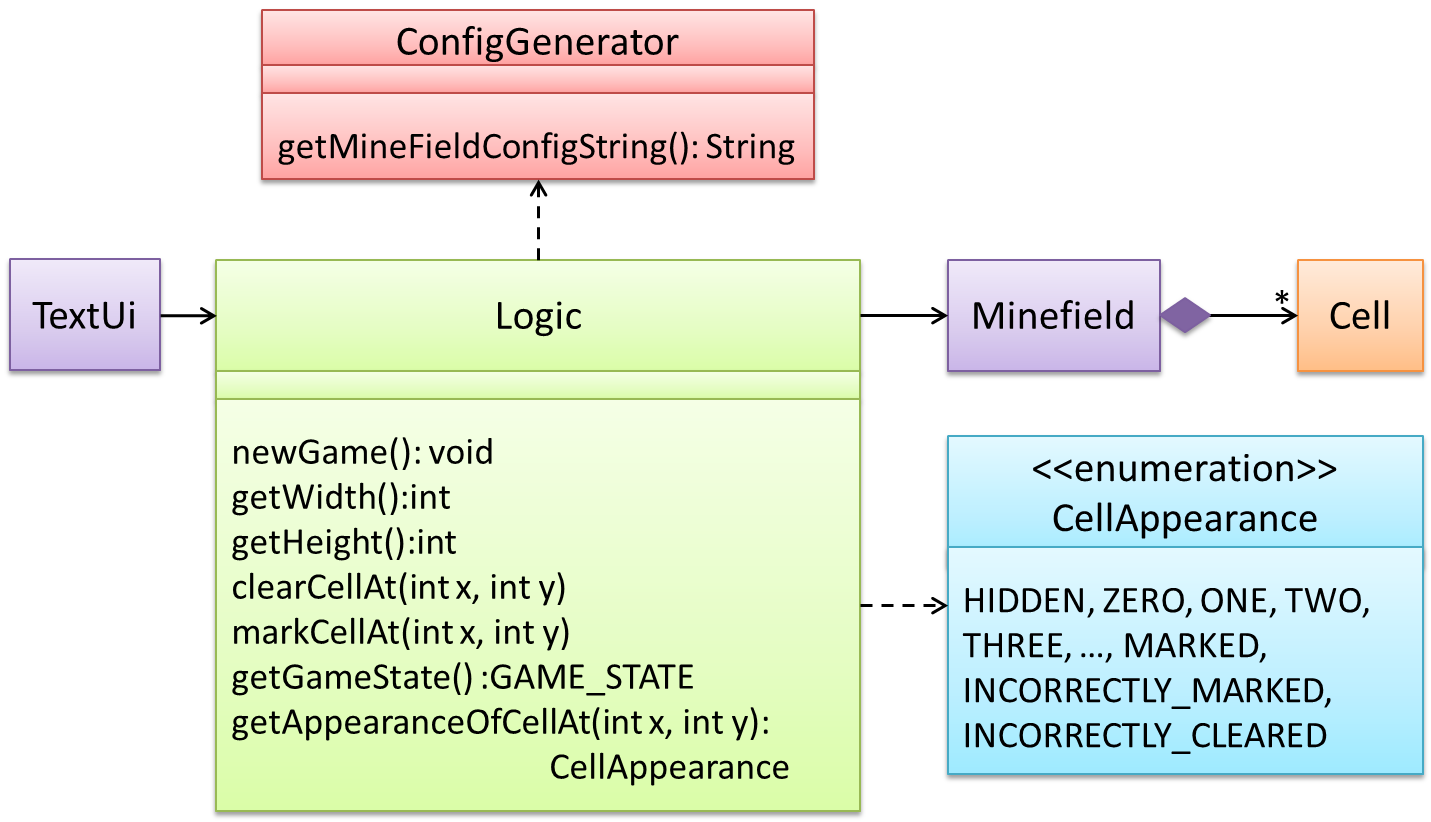
This interaction adds the following methods to the Logic class
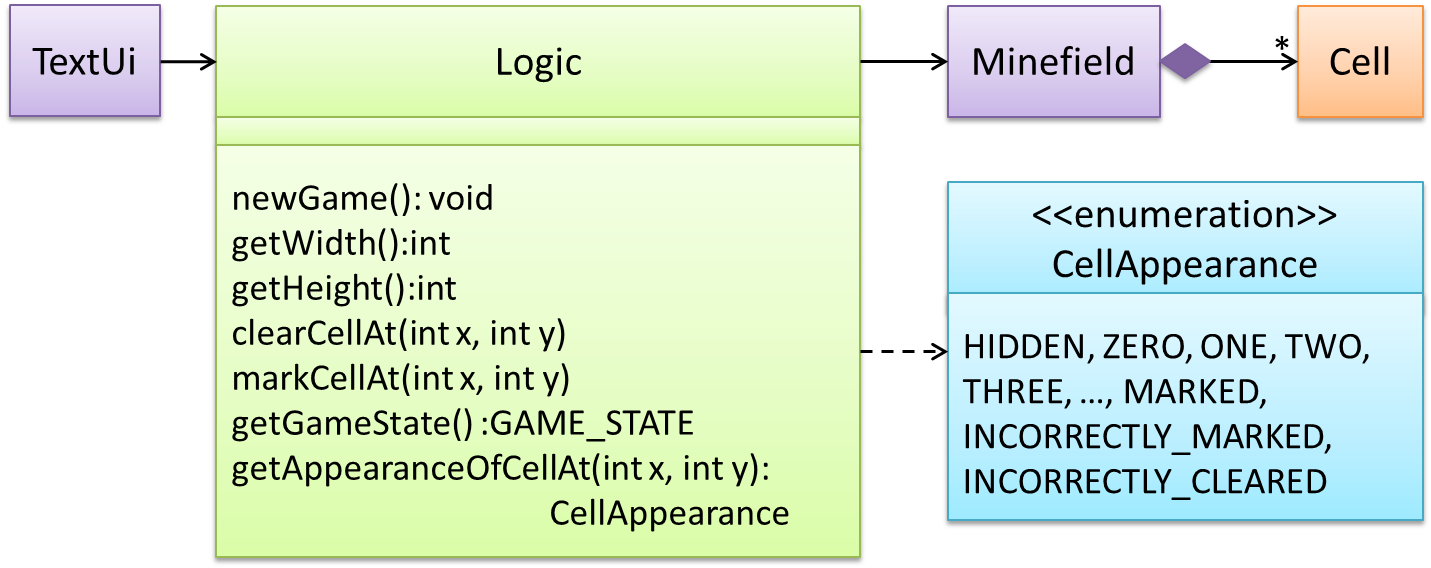
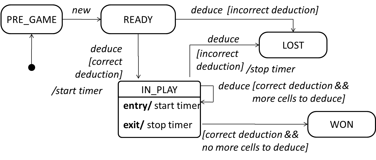
clearCellAt(int x, int y)markCellAt(int x, int y)getGameState() :GAME_STATE (GAME_STATE: READY, IN_PLAY, WON, LOST, …)
And it adds the following operation to Logic API:
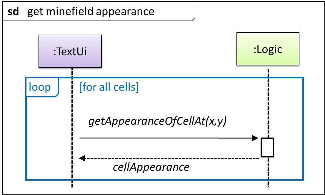
getAppearanceOfCellAt(int,int):CELL_APPEARANCE (CELL_APPEARANCE: HIDDEN, ZERO, ONE, TWO, THREE, …, MARKED, INCORRECTLY_MARKED, INCORRECTLY_CLEARED)
In the above design, TextUi does not access Cell objects directly. Instead, it gets values of type CELL_APPEARANCE from Logic to be displayed as a minefield to the player. Alternatively,
each cell or the entire Minefield can be passed directly to TextUi.
Here is the updated class diagram:
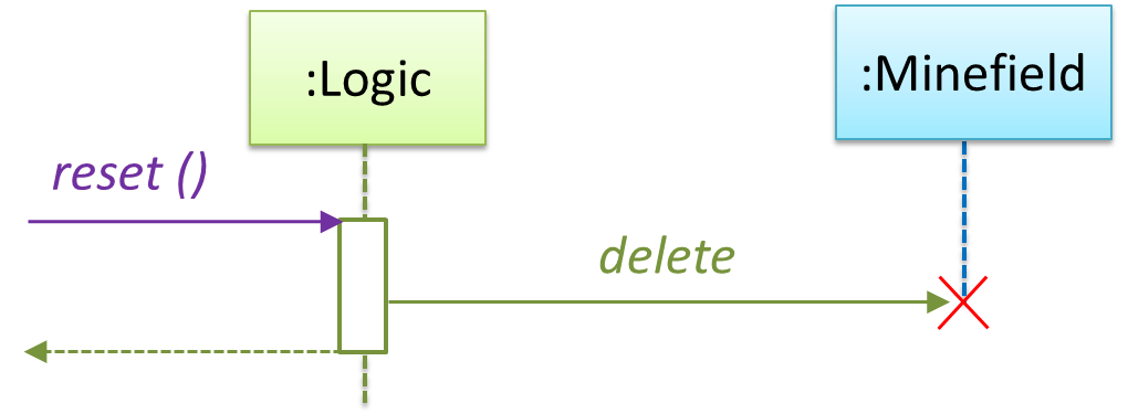
The above is for the case when Actor Player interacts with the system using a text UI. Additional operations (if any) required for the GUI can be discovered similarly. Suppose Logic supports a reset() operation. We can model it like this:
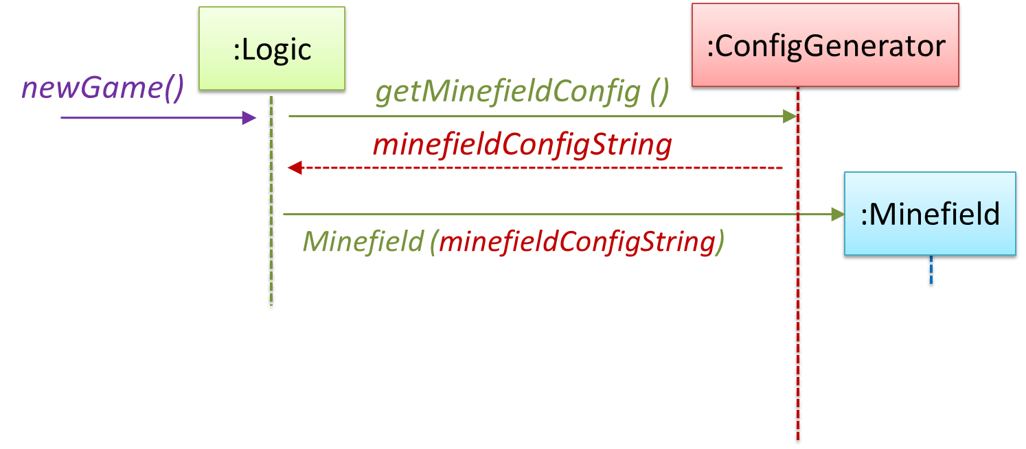
Our current model assumes that the Minefield object has enough information (i.e. H, W, and mine locations) to create itself.
An alternative is to have a ConfigGenerator object that generates a string containing the minefield information as shown below.
In addition, getWidth(), getHeight(), markCellAt(x,y) and clearCellAt(x,y) can be handled like this.
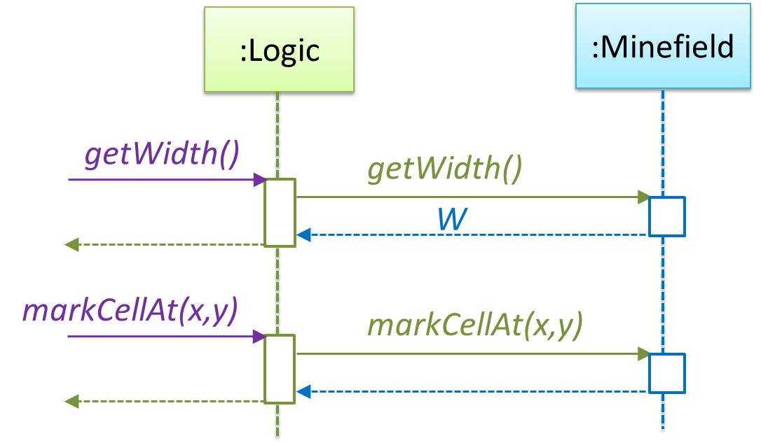
The updated class diagram:
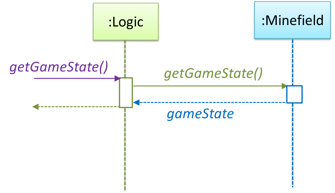
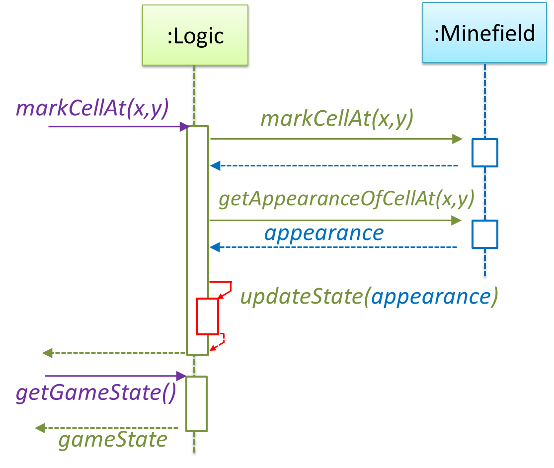
How is getGameState() operation supported? Given below are two ways (there could be other ways):
Minefield class knows the state of the game at any time. Logic class retrieves it from the Minefield class as and when required.Logic class maintains the state of the game at all times.
Here’s the SD for option 1.
Here’s the SD for option 2. Here, assume that the game state is updated after every mark/clear action.
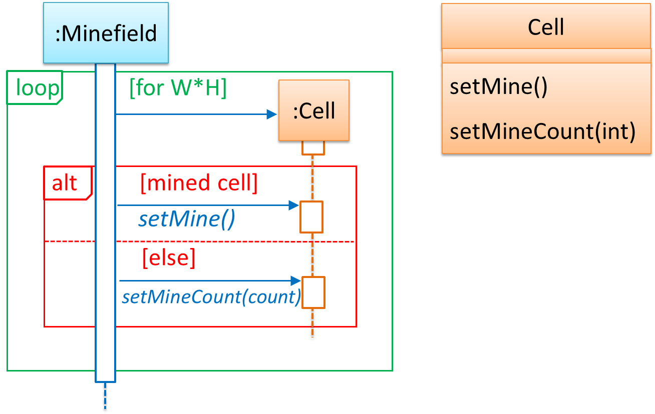
It is now time to explore what happens inside the Minefield constructor? One way is to design it as follows.
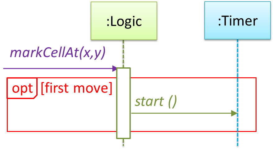
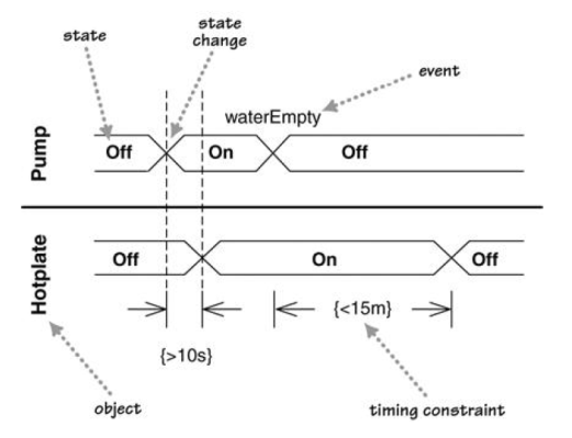
Now let us assume that Minesweeper supports a ‘timing’ feature.
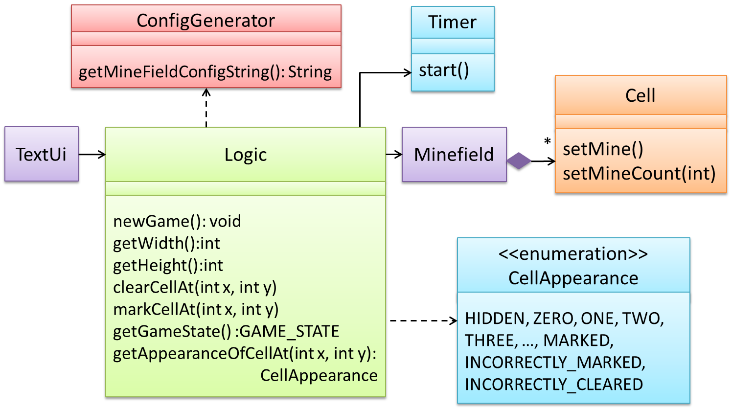
Updated class diagram:
💡 When designing components, it is not necessary to draw elaborate UML diagrams capturing all details of the design. They can be done as rough sketches. For example, draw sequence diagrams only when you are not sure which operations
are required by each class, or when you want to verify that your class structure can indeed support the required operations.


