Week 9 [Oct 15]
Todo
Admin info to read:
Overview: Move code towards v2.0 in small steps, start documenting design/implementation details in DG.
v1.2 Summary of Milestone
| Milestone | Minimum acceptable performance to consider as 'reached' |
|---|---|
| Contributed code to the product as described in mid-v1.2 progress guide | some code merged |
| Described implementation details in the Developer Guide | some text and some diagrams added to the developer guide (at least in a PR), comprising at least one page worth of content |
| v1.2 managed using GitHub features (issue tracker, milestones, etc.) | A new version git tagged v1.2 is in your repo.There is evidence of an attempt (even if not completely successful) to use GitHub features as described in |
Project Schedule Tracking
In general, use the issue tracker (Milestones, Issues, PRs, Tags, Releases, and Labels) for assigning, scheduling, and tracking all noteworthy project tasks, including user stories. Update the issue tracker regularly to reflect the current status of the project. You can also use GitHub's new Projects feature to manage the project, but keep it linked to the issue tracker as much as you can.
Using Issues:
-
Record each of the user stories you plan to deliver as an issue in the issue tracker. e.g.
Title: As a user I can add a deadline
Description: ... so that I can keep track of my deadlines -
Assign the
type.*andpriority.*labels to those issues. -
When you start implementing a story, break it down to tasks. Define reasonable sized, standalone tasks. A task should be able to done by one person, in a few hours. e.g.
- 👍 Good: Update class diagram in the project manual for v1.4
- 👎 Bad (reasons: not a one-person task, not small enough): Write the project manual
-
Write a descriptive title for the issue. e.g. Add support for the 'undo' command to the parser.
-
There is no need to break things into VERY small tasks. Keep them as big as possible, but they should be no bigger than what you are going to assign a single person to do within a week. eg.,
Implementing parser: too big because it cannot be done by a single person in a week.Implementing parser support for adding of floating tasks: appropriate size.
-
Do not track things taken for granted. e.g.,
push code to reposhould not be a task to track. In the example given under the previous point, it is taken for granted that the owner will also (a) test the code and (b) push to the repo when it is ready. Those two need not be tracked as separate tasks. -
Omit redundant details. In some cases, the summary/title is enough to describe the task. In that case, no need to repeat it in the description. There is no need for well-crafted and detailed descriptions for tasks. A minimal description is enough. Similarly, labels such as
prioritycan be omitted if you think they don't help you. -
Assign tasks to team members using the
assigneesfield. At any point, there should be some ongoing tasks and some pending tasks against each team member. -
Optionally, you can use
status.ongoinglabel to indicate issues currently ongoing.
Using Milestones:
-
Use GitHub milestones to indicate which issues are to be handled for which milestone by assigning issues to suitable milestones.
-
Set the deadlines for milestones (in GitHub). Your internal milestones can be set earlier than the deadlines we have set, to give you a buffer.
-
Note that you can change the milestone plan along the way as necessary.
Wrapping up a Milestone:
Here are the conditions to satisfy for a milestone to be considered properly wrapped up:
-
A working product tagged with the correct tag (e.g. v1.2) is pushed to the main repo.
-
All tests passing on Travis for the version tagged above.
-
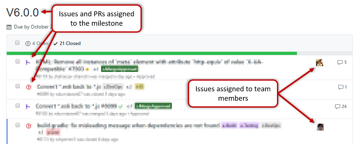
Milestone updated to match the product i.e. all issues completed and PRs merged for the milestone should be assigned to the milestone.
-
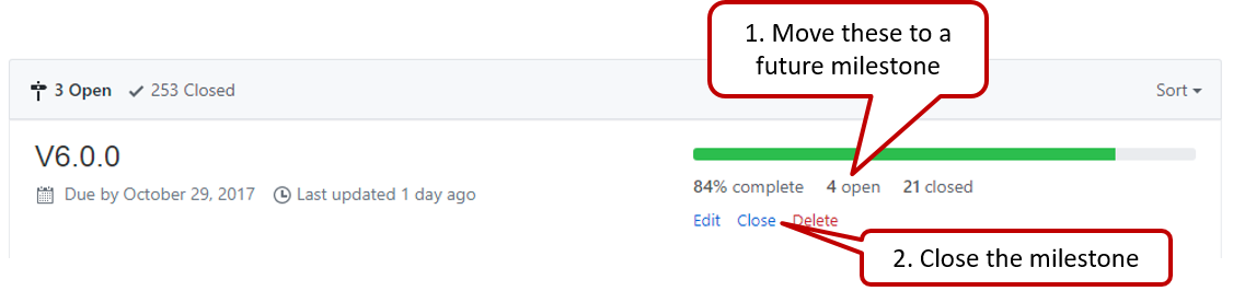
Milestone closed. If there are incomplete issues or unmerged PRs in the milestone, move them to a future milestone.
-
Optionally, issues for the next milestone are assigned to team members (this is not compulsory to do before the tutorial, but we recommend you to do it soon after the tutorial).
-
Optionally, future milestones are revised based on what you experienced in the current milestone e.g. if you could not finish all issues assigned to the current milestone, it is a sign that you overestimated how much you can do in a week, which means you might want to reduce the issues assigned to future milestones to match that observation.
-
Doing a 'release' on GitHub is optional for v1.1 and v1.2 but compulsory from v1.3.
v1.2 Project Management
- Manage, and close, the v1.2 milestone using GitHub.
v1.2 Product
- Merge some code into master (in the team repo).
💡 We use a tool called Reposense to extract out code written by each member in your final project submission.
v1.2 Documentation
-
User Guide: Update as necessary.
- If a feature has been released in this version, remove the
Coming in v2.0annotation from that feature. Also replace UI mock-ups with actual screenshots. - If a feature design has changed, update the descriptions accordingly.
- If a feature has been released in this version, remove the
-
Developer Guide:
- Each member should describe the implementation of at least one enhancement she has added (or planning to add).
Expected length: 1+ page per person - The description can contain things such as,
- How the feature is implemented.
- Why it is implemented that way.
- Alternatives considered.
- The stated objective is to explain the implementation to a future developer, but a hidden objective is to show evidence that you can document deeply-technical content using prose, examples, diagrams, code snippets, etc. appropriately. To that end, you may also describe features that you plan to implement in the future, even beyond v1.4 (hypothetically).
- For an example, see the description of the undo/redo feature implementation in the AddressBook-Level4 developer guide.
- Each member should describe the implementation of at least one enhancement she has added (or planning to add).
v1.2 Demo
Do an informal demo of the new feature during the tutorial. Each team member should demo their own work, using commit tagged as v1.2 in the master branch i.e. only features included in the current release should be demoed.
Outcomes
Design
W9.1 Can use models to conceptualize an OO solution
W9.1a Can explain how modelling can be used before implementation
Design → Modeling → Modeling a Solution →
Introduction
You can use models to analyze and design a software before you start coding.
Suppose You are planning to implement a simple minesweeper game that has a text based UI and a GUI. Given below is a possible OOP design for the game.

Before jumping into coding, you may want to find out things such as,
- Is this class structure is able to produce the behavior we want?
- What API should each class have?
- Do we need more classes?
To answer those questions, you can analyze the how the objects of these classes will interact with each other to produce the behavior you want.
W9.1b Can use simple class diagrams and sequence diagrams to model an OO solution
Design → Modeling → Modeling a Solution →
Basic
As mentioned in [
Design → Modeling → Modeling a Solution →
Introduction
You can use models to analyze and design a software before you start coding.
Suppose You are planning to implement a simple minesweeper game that has a text based UI and a GUI. Given below is a possible OOP design for the game.
Before jumping into coding, you may want to find out things such as,
- Is this class structure is able to produce the behavior we want?
- What API should each class have?
- Do we need more classes?
To answer those questions, you can analyze the how the objects of these classes will interact with each other to produce the behavior you want.
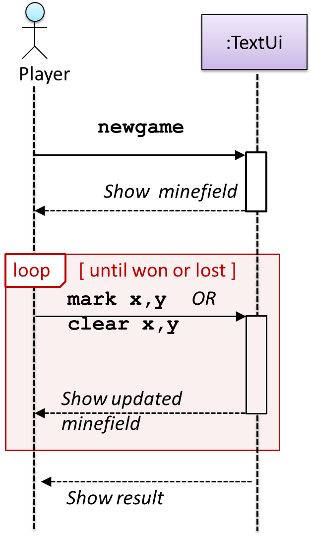
Let us start by modelling a sample interaction between the person playing the game and the TextUi object.
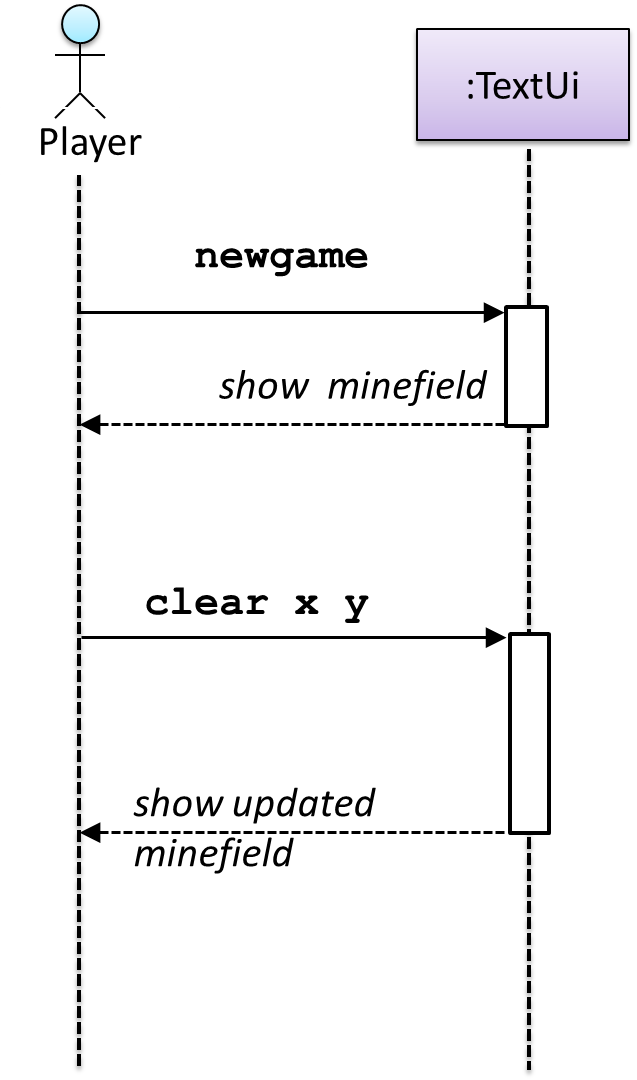
newgame and clear x y represent commands typed by the Player on the TextUi.
How does the TextUi object carry out the requests it has received from player? It would need to interact with other objects of the system. Because the Logic class is the one that controls the game logic,
the TextUi needs to collaborate with Logic to fulfill the newgame request. Let us extend the model to capture that interaction.
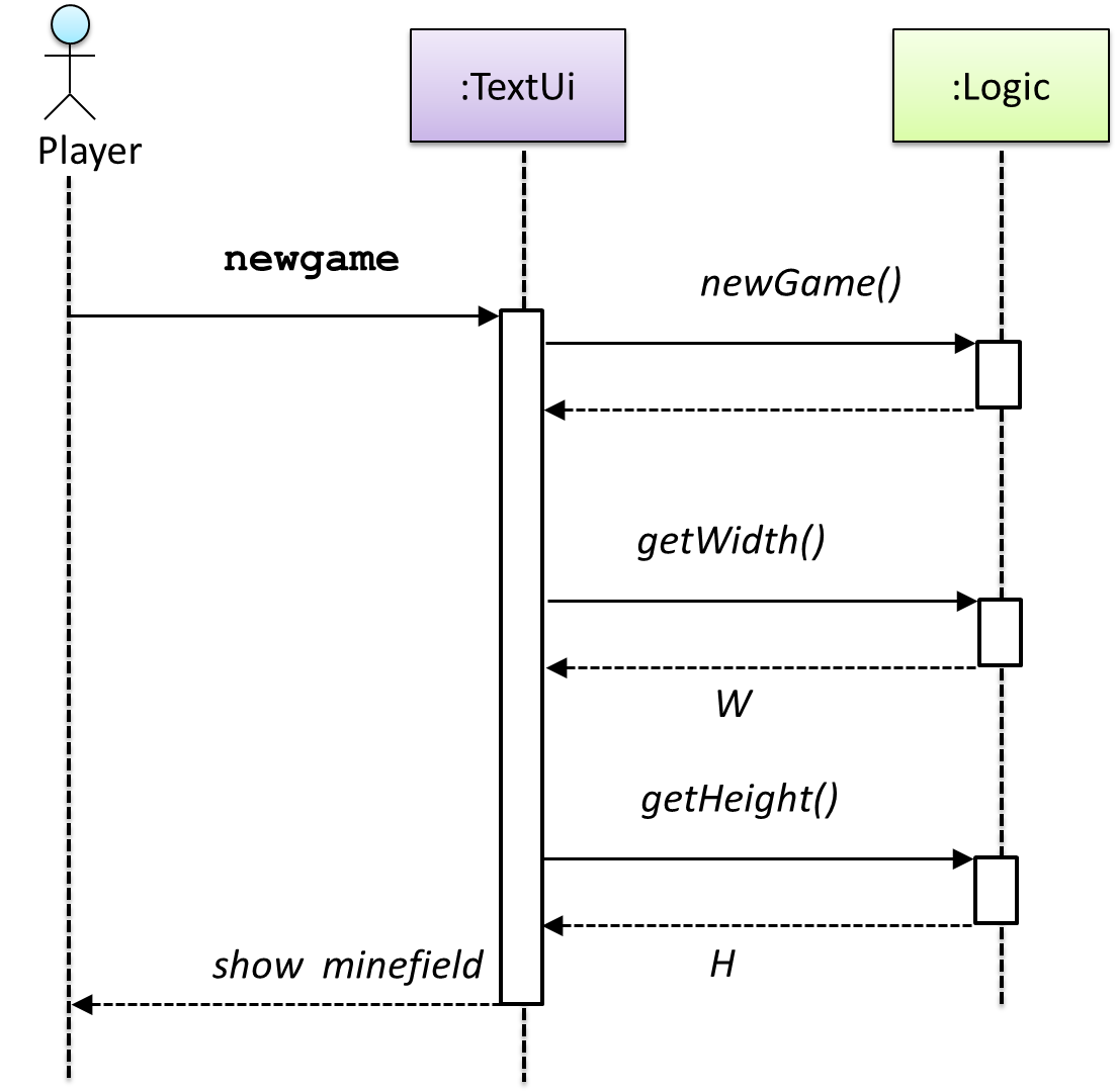
W = Width of the minefield; H = Height of the minefield
The above diagram assumes that W and H are the only information TextUi requires to display the minefield to the Player. Note that there could be other ways of doing this.
The
Logic methods we conceptualized in our modelling so far are:
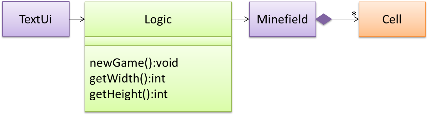
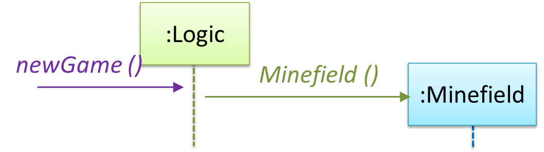
Now, let us look at what other objects and interactions are needed to support the newGame() operation. It is likely that a new Minefield object is created when the newGame() method is called.
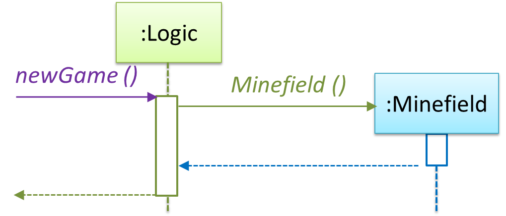
Note that the behavior of the Minefield constructor has been abstracted away. It can be designed at a later stage.
Given below are the interactions between the player and the Text UI for the whole game.
💡 Note that
Defining the architecture-level APIs for a small Tic-Tac-Toe game:
Evidence:
Use models to design/document future features of your project.
W9.1c Can use intermediate class diagram and sequence diagram concepts to model
an OO design
Design → Modeling → Modeling a Solution →
Intermediate
Continuing with the example in [
Design → Modeling → Modeling a Solution →
Basic
As mentioned in [
Design → Modeling → Modeling a Solution →
Introduction
You can use models to analyze and design a software before you start coding.
Suppose You are planning to implement a simple minesweeper game that has a text based UI and a GUI. Given below is a possible OOP design for the game.
Before jumping into coding, you may want to find out things such as,
- Is this class structure is able to produce the behavior we want?
- What API should each class have?
- Do we need more classes?
To answer those questions, you can analyze the how the objects of these classes will interact with each other to produce the behavior you want.
Let us start by modelling a sample interaction between the person playing the game and the TextUi object.
newgame and clear x y represent commands typed by the Player on the TextUi.
How does the TextUi object carry out the requests it has received from player? It would need to interact with other objects of the system. Because the Logic class is the one that controls the
game logic, the TextUi needs to collaborate with Logic to fulfill the newgame request. Let us extend the model to capture that interaction.
W = Width of the minefield; H = Height of the minefield
The above diagram assumes that W and H are the only information TextUi requires to display the minefield to the Player. Note that there could be other ways of doing
this.
The Logic methods we conceptualized in our modelling so far are:
Now, let us look at what other objects and interactions are needed to support the newGame() operation. It is likely that a new Minefield object is created when the newGame() method
is called.
Note that the behavior of the Minefield constructor has been abstracted away. It can be designed at a later stage.
Given below are the interactions between the player and the Text UI for the whole game.
💡 Note that
Defining the architecture-level APIs for a small Tic-Tac-Toe game:
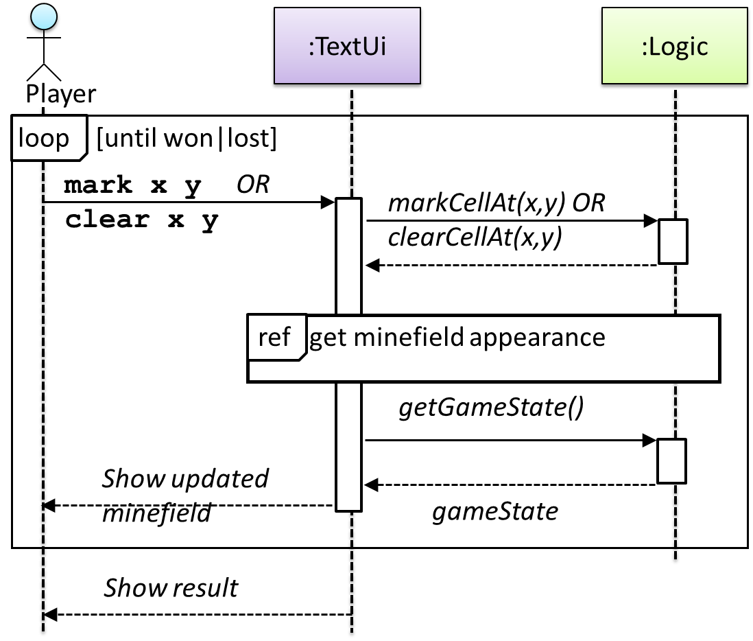
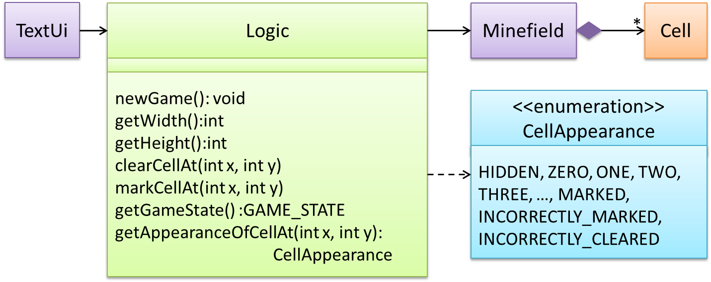
This interaction adds the following methods to the Logic class
clearCellAt(int x, int y)markCellAt(int x, int y)getGameState() :GAME_STATE (GAME_STATE: READY, IN_PLAY, WON, LOST, …)
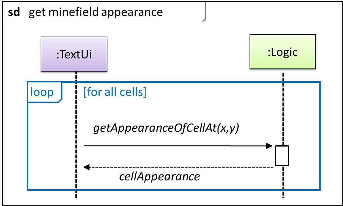
And it adds the following operation to Logic API:
getAppearanceOfCellAt(int,int):CELL_APPEARANCE (CELL_APPEARANCE: HIDDEN, ZERO, ONE, TWO, THREE, …, MARKED, INCORRECTLY_MARKED, INCORRECTLY_CLEARED)
In the above design, TextUi does not access Cell objects directly. Instead, it gets values of type CELL_APPEARANCE from Logic to be displayed as a minefield to the player. Alternatively,
each cell or the entire Minefield can be passed directly to TextUi.
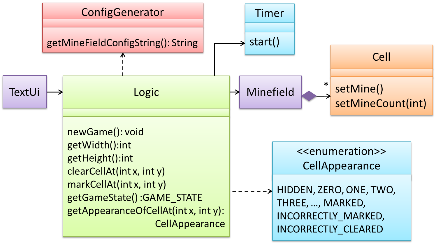
Here is the updated class diagram:
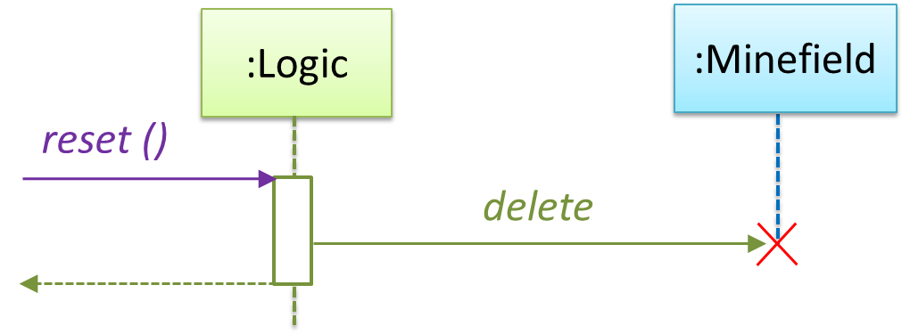
The above is for the case when Actor Player interacts with the system using a text UI. Additional operations (if any) required for the GUI can be discovered similarly. Suppose Logic supports a reset() operation. We can model it like this:
Our current model assumes that the Minefield object has enough information (i.e. H, W, and mine locations) to create itself.
An alternative is to have a ConfigGenerator object that generates a string containing the minefield information as shown below.
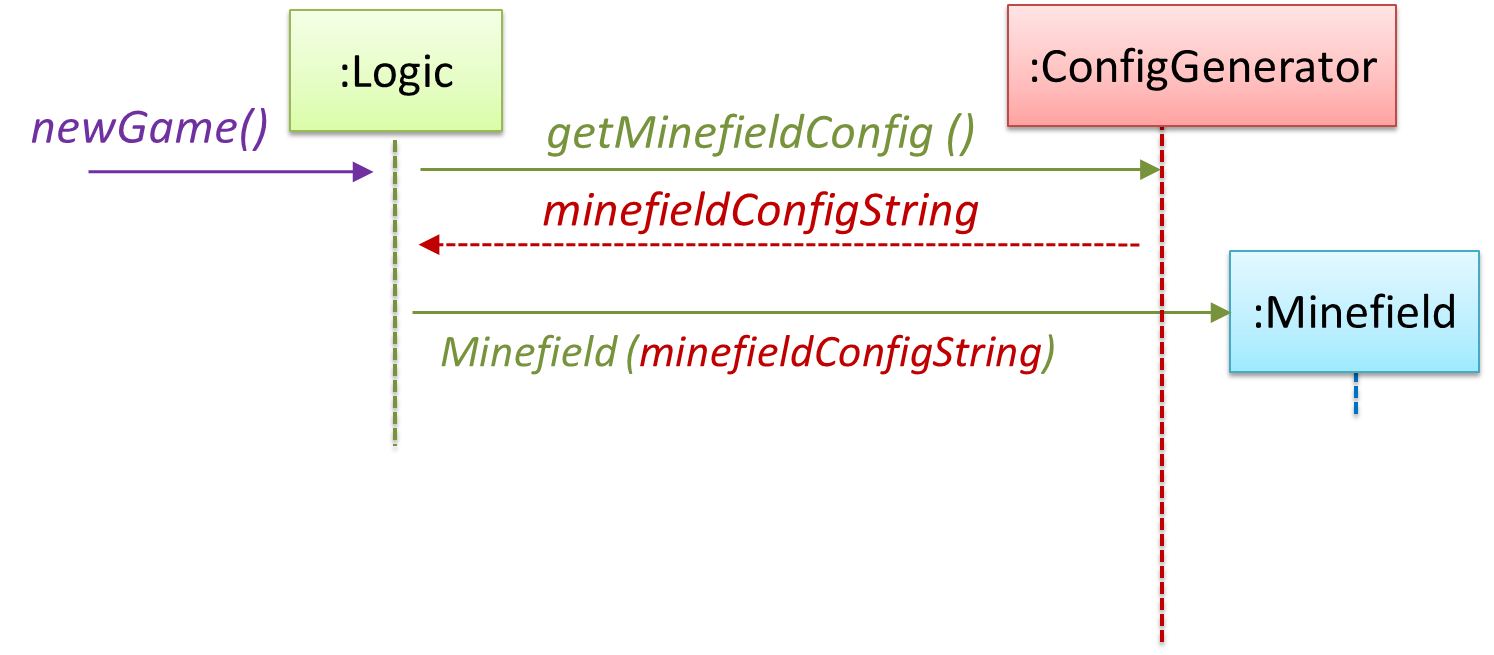
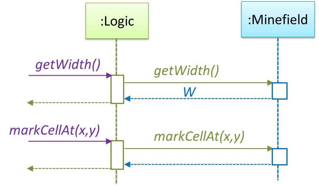
In addition, getWidth(), getHeight(), markCellAt(x,y) and clearCellAt(x,y) can be handled like this.
The updated class diagram:
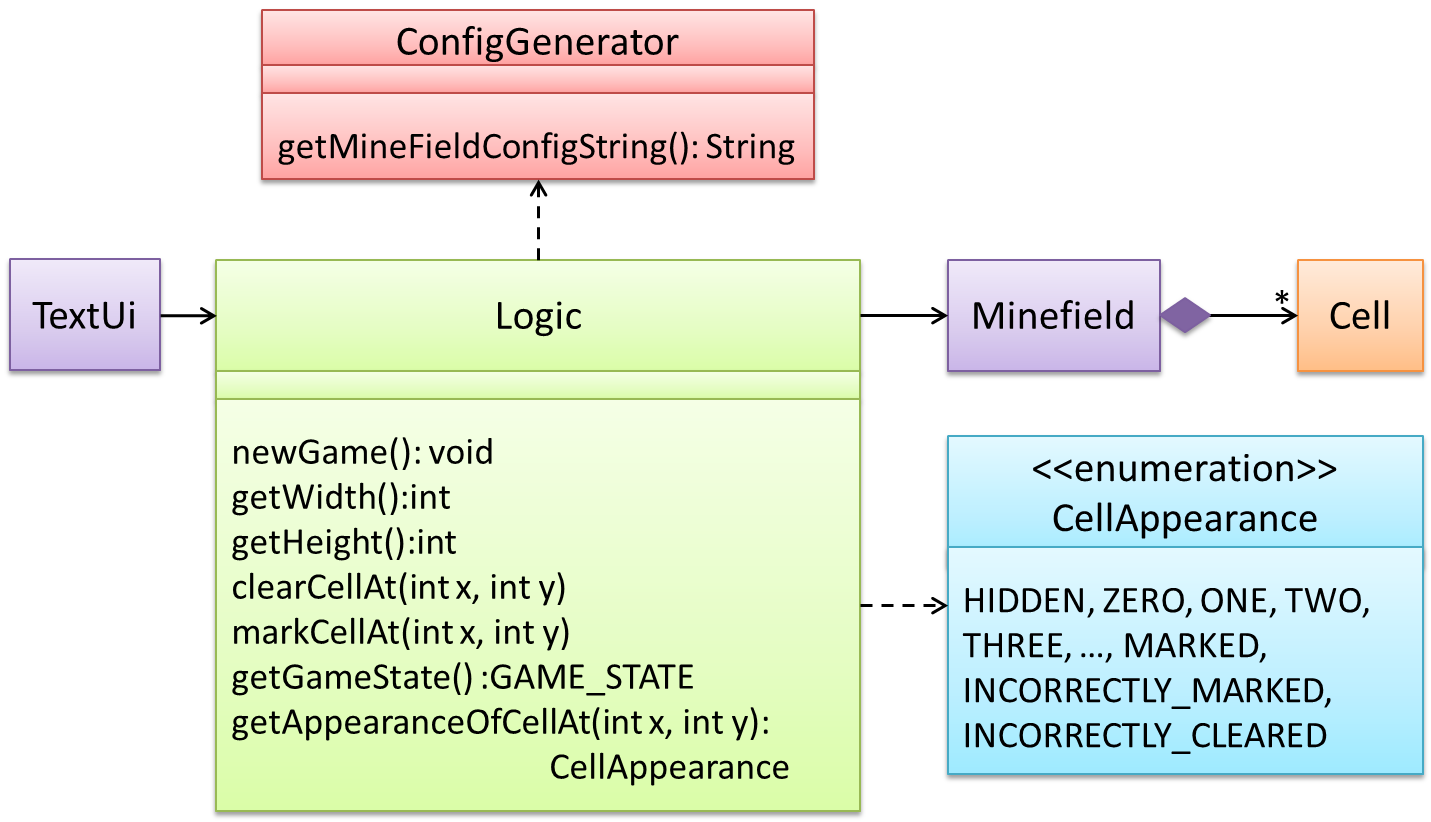
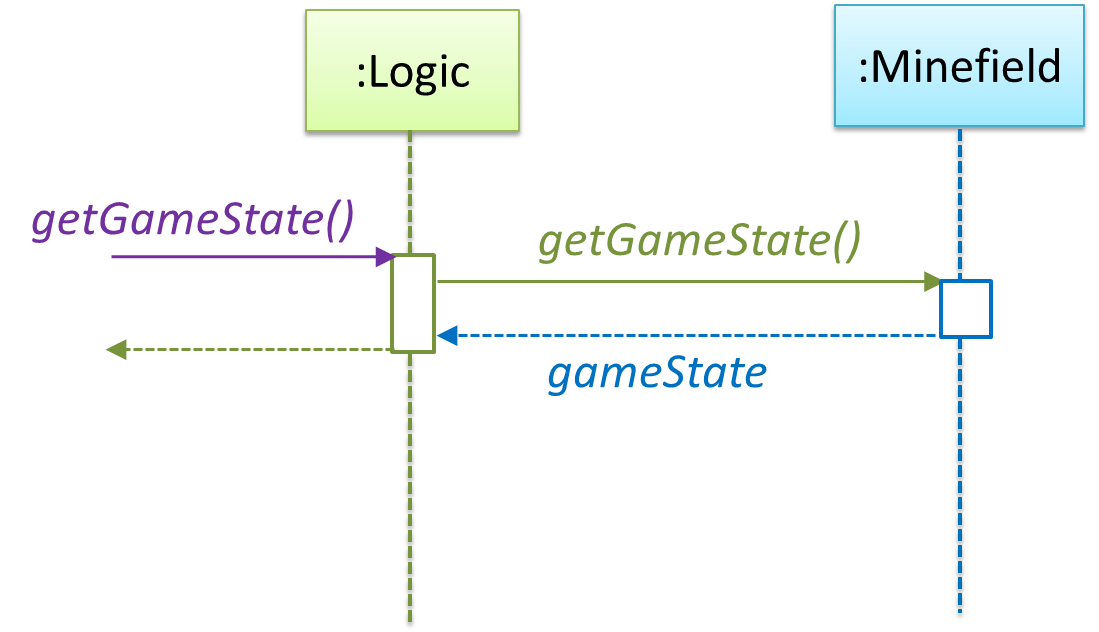
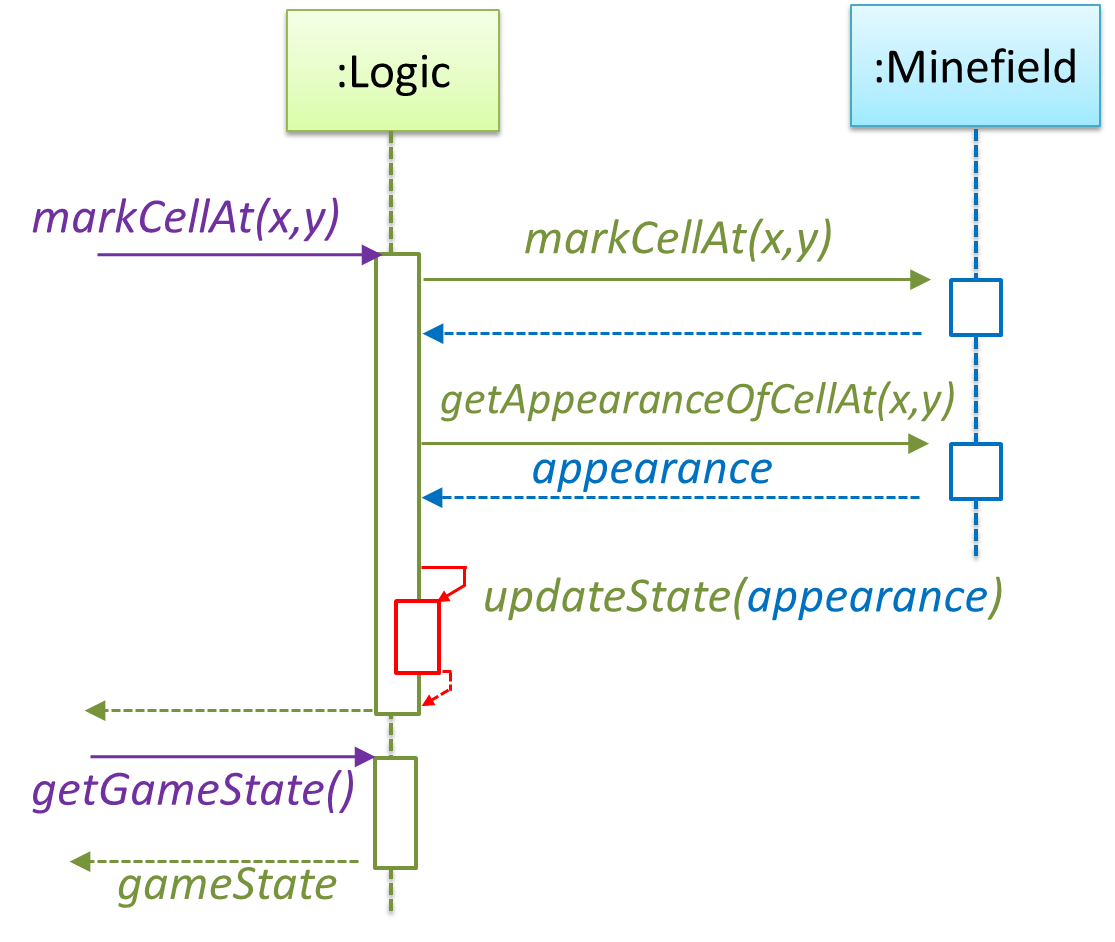
How is getGameState() operation supported? Given below are two ways (there could be other ways):
Minefieldclass knows the state of the game at any time.Logicclass retrieves it from theMinefieldclass as and when required.Logicclass maintains the state of the game at all times.
Here’s the SD for option 1.
Here’s the SD for option 2. Here, assume that the game state is updated after every mark/clear action.
It is now time to explore what happens inside the Minefield constructor? One way is to design it as follows.
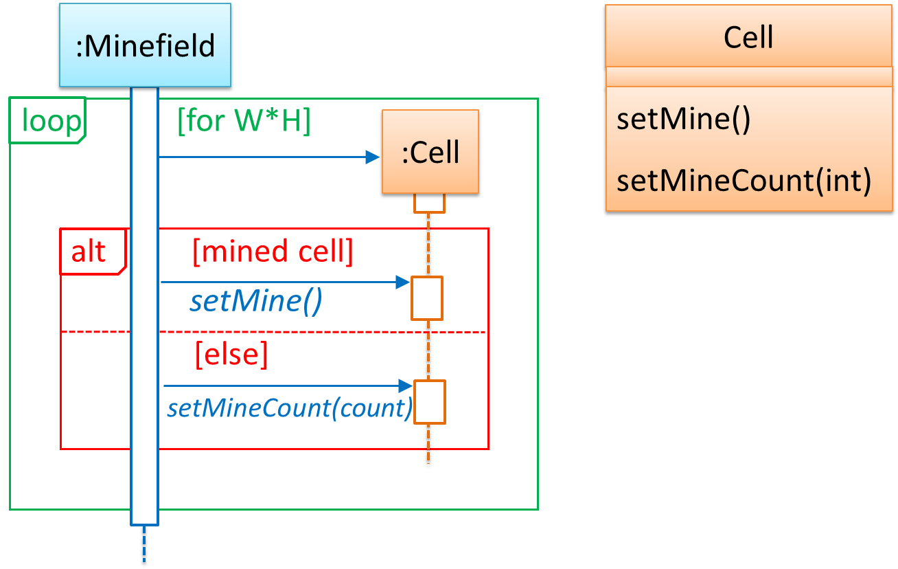
Now let us assume that Minesweeper supports a ‘timing’ feature.
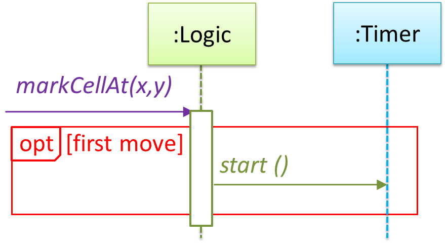
Updated class diagram:
💡 When designing components, it is not necessary to draw elaborate UML diagrams capturing all details of the design. They can be done as rough sketches. For example, draw sequence diagrams only when you are not sure which operations are required by each class, or when you want to verify that your class structure can indeed support the required operations.
Evidence:
Use models to design/document future features of your project.
W9.2 Can use intermediate-level design principles
How Polymorphism Works
W9.2a Can explain substitutability
Paradigms → Object Oriented Programming → Inheritance →
Substitutability
Every instance of a subclass is an instance of the superclass, but not vice-versa. As a result, inheritance allows substitutability : the ability to substitute a child class object where a parent class object is expected.
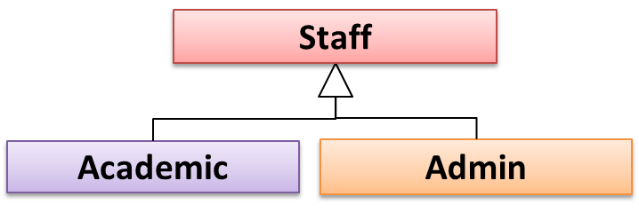
an Academic is an instance of a Staff, but a Staff is not necessarily an instance of an Academic. i.e. wherever an object of the superclass is
expected, it can be substituted by an object of any of its subclasses.
The following code is valid because an AcademicStaff object is substitutable as a Staff object.
Staff staff = new AcademicStaff (); // OK
But the following code is not valid because staff is declared as a Staff type and therefore its value may or may not be of type AcademicStaff, which is the type expected by variable academicStaff.
Staff staff;
...
AcademicStaff academicStaff = staff; // Not OK
W9.2b Can explain dynamic and static binding
Paradigms → Object Oriented Programming → Inheritance →
Dynamic and Static Binding
Dynamic Binding (
Paradigms → Object Oriented Programming → Inheritance →
Overriding
Method overriding is when a sub-class changes the behavior inherited from the parent class by re-implementing the method. Overridden methods have the same name, same type signature, and same return type.
Consider the following case of EvaluationReport class inheriting the Report class:
Report methods |
EvaluationReport methods |
Overrides? |
|---|---|---|
print() |
print() |
Yes |
write(String) |
write(String) |
Yes |
read():String |
read(int):String |
No. Reason: the two methods have different signatures; This is a case of |
Paradigms → Object Oriented Programming → Inheritance →
Overloading
Method overloading is when there are multiple methods with the same name but different type signatures. Overloading is used to indicate that multiple operations do similar things but take different parameters.
Type Signature: The type signature of an operation is the type sequence of the parameters. The return type and parameter names are not part of the type signature. However, the parameter order is significant.
| Method | Type Signature |
|---|---|
int add(int X, int Y) |
(int, int) |
void add(int A, int B) |
(int, int) |
void m(int X, double Y) |
(int, double) |
void m(double X, int Y) |
(double, int) |
In the case below, the calculate method is overloaded because the two methods have the same name but different type signatures (String) and (int)
calculate(String): voidcalculate(int): void
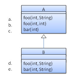
Which of these methods override another method? A is the parent class. B inherits A.
- a
- b
- c
- d
- e
d
Explanation: Method overriding requires a method in a child class to use the same method name and same parameter sequence used by one of its ancestors
Consider the code below. The declared type of s is Staff and it appears as if the adjustSalary(int) operation of the Staff class is invoked.
void adjustSalary(int byPercent) {
    for (Staff s: staff) {
        s.adjustSalary(byPercent);
    }
}
However, at runtime s can receive an object of any subclass of Staff. That means the adjustSalary(int) operation of the actual subclass object will be called. If the subclass does not override that operation,
the operation defined in the superclass (in this case, Staff class) will be called.
Static binding (aka early binding): When a method call is resolved at compile time.
In contrast,
Paradigms → Object Oriented Programming → Inheritance →
Overloading
Method overloading is when there are multiple methods with the same name but different type signatures. Overloading is used to indicate that multiple operations do similar things but take different parameters.
Type Signature: The type signature of an operation is the type sequence of the parameters. The return type and parameter names are not part of the type signature. However, the parameter order is significant.
| Method | Type Signature |
|---|---|
int add(int X, int Y) |
(int, int) |
void add(int A, int B) |
(int, int) |
void m(int X, double Y) |
(int, double) |
void m(double X, int Y) |
(double, int) |
In the case below, the calculate method is overloaded because the two methods have the same name but different type signatures (String) and (int)
calculate(String): voidcalculate(int): void
Note how the constructor is overloaded in the class below. The method call new Account() is bound to the first constructor at compile time.
class Account {

    Account () {
        // Signature: ()
        ...
    }

    Account (String name, String number, double balance) {
        // Signature: (String, String, double)
        ...
    }
}
Similarly, the calcuateGrade method is overloaded in the code below and a method call calculateGrade("A1213232") is bound to the second implementation, at compile
time.
void calculateGrade (int[] averages) { ... }
void calculateGrade (String matric) { ... }
W9.2c Can explain how substitutability operation overriding, and dynamic binding
relates to polymorphism
Paradigms → Object Oriented Programming → Polymorphism →
How
Three concepts combine to achieve polymorphism: substitutability, operation overriding, and dynamic binding.
- Substitutability: Because of substitutability, you can write code that expects object of a parent class and yet use that code with objects of child classes. That is how polymorphism is able to treat objects of different types as one type.
- Overriding: To get polymorphic behavior from an operation, the operation in the superclass needs to be overridden in each of the subclasses. That is how overriding allows objects of different subclasses to display different behaviors in response to the same method call.
- Dynamic binding: Calls to overridden methods are bound to the implementation of the actual object's class dynamically during the runtime. That is how the polymorphic code can call the method of the parent class and yet execute the implementation of the child class.
Which one of these is least related to how OO programs achieve polymorphism?
(c)
Explanation: Operation overriding is the one that is related, not operation overloading.
Evidence:
Explain how substitutability operation overriding, and dynamic binding relates to polymorphism by taking a real example from the project.
Design Approaches
W9.2d Can explain top-down and bottom-up design
Design → Introduction →
Top-Down and Bottom-Up Design
Multi-level design can be done in a top-down manner, bottom-up manner, or as a mix.
- Top-down: Design the high-level design first and flesh out the lower levels later. This is especially useful when designing big and novel systems where the high-level design needs to be stable before lower levels can be designed.
- Bottom-up: Design lower level components first and put them together to create the higher-level systems later. This is not usually scalable for bigger systems. One instance where this approach might work is when designing a variations of an existing system or re-purposing existing components to build a new system.
- Mix: Design the top levels using the top-down approach but switch to a bottom-up approach when designing the bottom levels.
Top-down design is better than bottom-up design.
False
Explanation: Not necessarily. It depends on the situation. Bottom-up design may be preferable when there are lot of existing components we want to reuse.
W9.2e Can explain agile design
Design Approaches → Agile Design →
Agile Design
Agile design can be contrasted with full upfront design in the following way:
Agile designs are emergent, they’re not defined up front. Your overall system design will emerge over time, evolving to fulfill new requirements and take advantage of new technologies as appropriate. Although you will often do some initial architectural modeling at the very beginning of a project, this will be just enough to get your team going. This approach does not produce a fully documented set of models in place before you may begin coding. -- adapted from agilemodeling.com
Agile design camp expects the design to change over the product’s lifetime.
True
Explanation: Yes, that is why they do not believe in spending too much time creating a detailed and full design at the very beginning. However, the architecture is expected to remain relatively stable even in the agile design approach.
More Design Principles
W9.2f Can explain Liskov Substitution Principle
Supplmentary → Principles →
Liskov Substitution Principle
Liskov Substitution Principle (LSP): Derived classes must be substitutable for their base classes. -- proposed by Barbara Liskov
LSP sounds same as
Paradigms → Object Oriented Programming → Inheritance →
Substitutability
Every instance of a subclass is an instance of the superclass, but not vice-versa. As a result, inheritance allows substitutability : the ability to substitute a child class object where a parent class object is expected.
an Academic is an instance of a Staff, but a Staff is not necessarily an instance of an Academic. i.e. wherever an object of the superclass
is expected, it can be substituted by an object of any of its subclasses.
The following code is valid because an AcademicStaff object is substitutable as a Staff object.
Staff staff = new AcademicStaff (); // OK
But the following code is not valid because staff is declared as a Staff type and therefore its value may or may not be of type AcademicStaff, which is the type expected by variable academicStaff.
Staff staff;
...
AcademicStaff academicStaff = staff; // Not OK
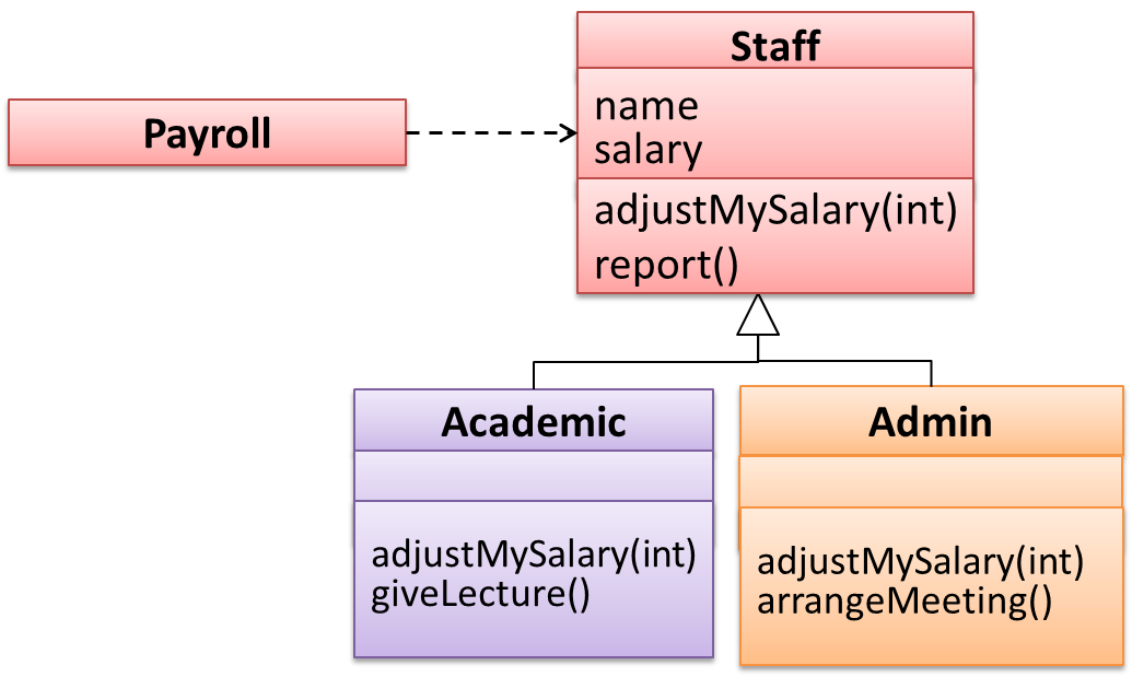
Suppose the Payroll class depends on the adjustMySalary(int percent) method of the Staff class. Furthermore, the Staff class states that the
adjustMySalary method will work for all positive percent values. Both Admin and Academic classes override the adjustMySalary method.
Now consider the following:
Admin#adjustMySalarymethod works for both negative and positive percent values.Academic#adjustMySalarymethod works for percent values1..100only.
In the above scenario,
Adminclass follows LSP because it fulfillsPayroll’s expectation ofStaffobjects (i.e. it works for all positive values). SubstitutingAdminobjects for Staff objects will not break thePayrollclass functionality.Academicclass violates LSP because it will not work for percent values over100as expected by thePayrollclass. SubstitutingAcademicobjects forStaffobjects can potentially break thePayrollclass functionality.
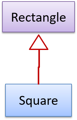
The Rectangle#resize() can take any integers for height and width. This contract is violated by the subclass Square#resize() because it does
not accept a height that is different from the width.
class Rectangle {
    ...
    /** sets the size to given height and width*/
    void resize(int height, int width){
        ...
    }
}


class Square extends Rectangle {

    @Override
    void resize(int height, int width){
        if (height != width) {
            //error
       }
    }
}
Now consider the following method that is written to work with the Rectangle class.
void makeSameSize(Rectangle original, Rectangle toResize){
    toResize.resize(original.getHeight(), original.getWidth());
}
This code will fail if it is called as maekSameSize(new Rectangle(12,8), new Square(4, 4)) That is, Square class is not substitutable for the Rectangle class.
If a subclass imposes more restrictive conditions than its parent class, it violates Liskov Substitution Principle.
True.
Explanation: If the subclass is more restrictive than the parent class, code that worked with the parent class may not work with the child class. Hence, the substitutability does not exist and LSP has been violated.
Evidence:
Give an example from the project where LSP is followed. Explain what kind of a change to that code will violate LSP e.g. Here, the superclass X and the subclass Y follow LSP. But if we change X in this way, or Y in this way, it will no longer follow LSP
W9.2g Can explain interface segregation principle
Supplmentary → Principles →
Interface Segregation Principle
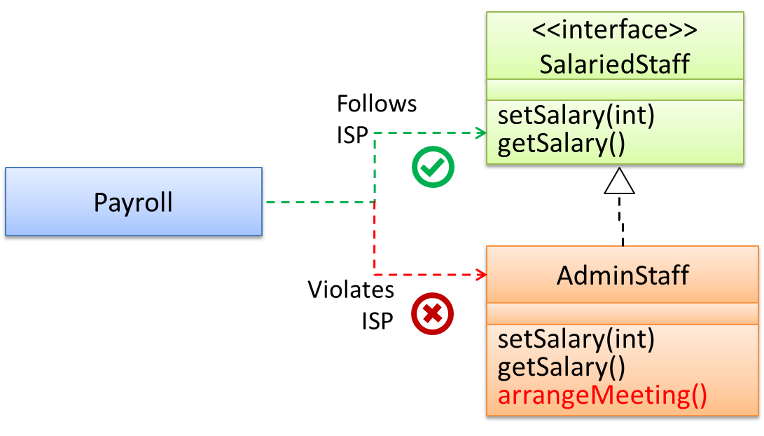
Interface Segregation Principle (ISP): No client should be forced to depend on methods it does not use.
The Payroll class should not depend on the AdminStaff class because it does not use the arrangeMeeting() method. Instead, it should depend on the SalariedStaff interface.
public class Payroll {
    //...
    private void adjustSalaries(AdminStaff adminStaff){ //violates ISP
        //...
    }

}
public class Payroll {
    //...
    private void adjustSalaries(SalariedStaff staff){ //does not violate ISP
        //...
    }
}
W9.2h Can explain dependency inversion principle (DIP)
Supplmentary → Principles →
Dependency Inversion Principle
The Dependency Inversion Principle states that,
- High-level modules should not depend on low-level modules. Both should depend on abstractions.
- Abstractions should not depend on details. Details should depend on abstractions.
Example:
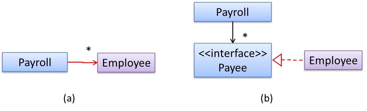
In design (a), the higher level class Payroll depends on the lower level class Employee, a violation of DIP. In design (b), both Payroll and Employee depends on the Payee interface
(note that inheritance is a dependency).
Design (b) is more flexible (and less coupled) because now the Payroll class need not change when the Employee class changes.
Which of these statements is true about the Dependency Inversion Principle.
- a. It can complicate the design/implementation by introducing extra abstractions, but it has some benefits.
- b. It is often used during testing, to replace dependencies with mocks.
- c. It reduces dependencies in a design.
- d. It advocates making higher level classes to depend on lower level classes.
Explanation: Replacing dependencies with mocks is Dependency Injection, not DIP. DIP does not reduce dependencies, rather, it changes the direction of dependencies. Yes, it can introduce extra abstractions but often the benefit can outweigh the extra complications.
Implementation
W9.3 Can implement association classes
W9.3a Can explain the meaning of association classes
Paradigms → Object Oriented Programming → Associations →
Association Classes
An association class represents additional information about an association. It is a normal class but plays a special role from a design point of view.
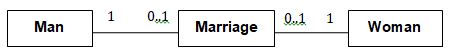
A Man class and a Woman class is linked with a ‘married to’ association and there is a need to store the date of marriage. However, that data is related to the association
rather than specifically owned by either the Man object or the Woman object. In such situations, an additional association class can be introduced, e.g. a Marriage class, to store such information.
Implementing association classes
There is no special way to implement an association class. It can be implemented as a normal class that has variables to represent the endpoint of the association it represents.
In the code below, the Transaction class is an association class that represent a transaction between a Person who is the seller and another Person who is
the buyer.
class Transaction{

    //all fields are compulsory
    Person seller;
    Person buyer;
    Date date;
    String receiptNumber;

    Marriage (Person seller, Person buyer, Date date, String receiptNumber){
        //set fields
    }
}
Which one of these is the suitable as an Association Class?
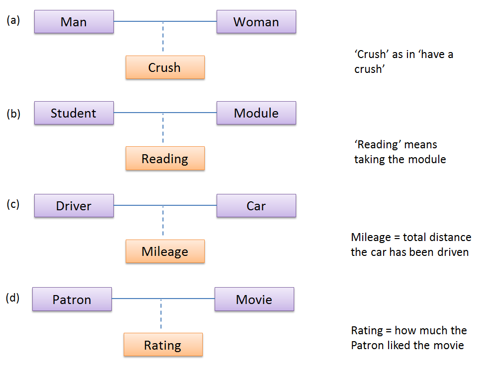
- a
- b
- c
- d
(a)(b)(c)(d)
Explanation: Mileage is a property of the car, and not specifically about the association between the Driver and the Car. If Mileage was defined as the total number of miles that car was driven by that driver, then it would be suitable as an association class.
Evidence:
Give more examples of association classes, preferably related to your project.
W9.3b Can interpret association classes in class diagrams
Tools → UML → Class Diagrams → Association Classes →
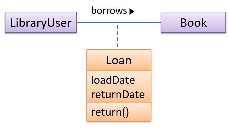
Association Classes
Association classes are denoted as a connection to an association link using a dashed line as shown below.
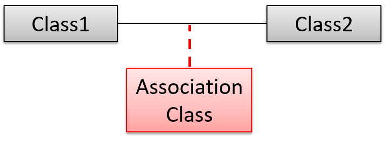
In this example Loan is an association class because it stores information about the borrows association between the User and the Book.
W9.4 Can use defensive programming
W9.4a Can explain defensive programming
Implementation → Error Handling → Defensive Programming →
What
A defensive programmer codes under the assumption "if we leave room for things to go wrong, they will go wrong". Therefore, a defensive programmer proactively tries to eliminate any room for things to go wrong.
Consider a MainApp#getConfig() a method that returns a Config object containing configuration data. A typical implementation is given below:
class MainApp{
    Config config;

    /** Returns the config object */
    Config getConfig(){
        return config;
    }
}
If the returned Config object is not meant to be modified, a defensive programmer might use a more defensive implementation given below. This is more defensive because even if the returned Config object is modified (although it is not meant to be) it will not affect the config object inside the MainApp object.
    /** Returns a copy of the config object */
    Config getConfig(){
        return config.copy(); //return a defensive copy
    }
W9.4b Can use defensive coding to enforce compulsory associations
Implementation → Error Handling → Defensive Programming →
Enforcing Compulsory Associations
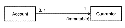
Consider two classes, Account and Guarantor, with an association as shown in the following diagram:
Example:
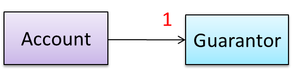
Here, the association is compulsory i.e. an Account object should always be linked to a Guarantor. One way to implement this is to simply use a reference variable, like this:
class Account {
    Guarantor guarantor;

    void setGuarantor(Guarantor g) {
        guarantor = g;
    }
}
However, what if someone else used the Account class like this?
Account a = new Account();
a.setGuarantor(null);
This results in an Account without a Guarantor! In a real banking system, this could have serious consequences! The code here did not try to prevent such a thing from happening. We can make the code
more defensive by proactively enforcing the multiplicity constraint, like this:
class Account {
    private Guarantor guarantor;

    public Account(Guarantor g){
        if (g == null) {
            stopSystemWithMessage("multiplicity violated. Null Guarantor");
        }
        guarantor = g;
    }
    public void setGuarantor (Guarantor g){
        if (g == null) {
            stopSystemWithMessage("multiplicity violated. Null Guarantor");
        }
        guarantor = g;
    }
    …
}
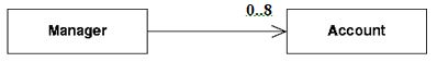
For the Manager class shown below, write an addAccount() method that
- restricts the maximum number of Accounts to 8
- avoids adding duplicate Accounts
import java.util.*;

public class Manager {
    private ArrayList< Account > theAccounts ;

    public void addAccount(Account acc) throws Exception {
        if (theAccounts.size( ) == 8){
            throw new Exception ("adding more than 8 accounts");
        }

        if (!theAccounts.contains(acc)) {
            theAccounts.add(acc);
        }
    }

    public void removeAccount(Account acc) {
        theAccounts.remove(acc);
    }
}
Implement the classes defensively with appropriate references and operations to establish the association among the classes. Follow the defensive coding approach. Let the Marriage class handle setting/removal
of reference.
public class Marriage {
    private Man husband = null;
    private Woman wife = null;

    // extra information like date etc can be added

    public Marriage(Man m, Woman w) throws Exception {
        if (m == null || w == null) {
            throw new Exception("no man/woman");
        }
        if (m.isMarried() || w.isMarried()) {
            throw new Exception("already married");
        }
        husband = m;
        m.enterMarriage(this);
        wife = w;
        w.enterMarriage(this);
    }

    public Man getHusband() throws Exception {
        if(husband == null) {
            throw new Exception("error state");
        } else {
            return husband;
        }
    }

    public Woman getWife() throws Exception {
        if(wife == null) {
            throw new Exception("error state");
        } else {
            return wife;
        }
    }

    // removal of both ends of 'Marriage'
    public void divorce() throws Exception {
        if (husband==null || wife==null) {
            throw new Exception("no marriage");
        }
        husband.removeFromMarriage(this);
        husband = null;
        wife.removeFromMarriage(this);
        wife = null;
    }
}
Give a suitable defensive implementation to the Account class in the following class diagram. Note that “{immutable}” means once the association is formed, it cannot be changed.
class Account {
    private Guarantor myGuarantor; // should not be public

    public Account(Guarantor g){
        if (g==null) {
            haltWithErrorMessage(“Account must have a guarantor”);
        }
        myGuarantor = g;
    }
    // there should not be a setGuarantor method
}
class City{
    Country country;

    void setCountry(Country country){
        this.country = country;
    }
}
This is a defensive implementation of the association.
False
Explanation: While the design requires a City to be connected to exactly one Country, the code allows it to be connected to zero Country objects (by passing null to the setCountry() method).
W9.4c Can use defensive coding to enforce 1-to-1 associations
Implementation → Error Handling → Defensive Programming →
Enforcing 1-to-1 Associations
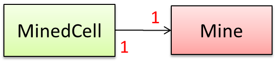
Consider the association given below. A defensive implementation requires to ensure a MinedCell cannot exist without a Mine and vice versa which requires simultaneous object creation. However, Java can
only create one object at a time. Given below are two alternatives implementations, both of which violate the multiplicity for a short period of time.
Option 1:
class MinedCell {
    private Mine mine;

    public MinedCell(Mine m){
        if (m == null) {
            showError();
        }
        mine = m;
    }
    …
}
Option 1 forces us to keep a Mine without a MinedCell (until the MinedCell is created).
Option 2:
class MinedCell {
    private Mine mine;

    public MinedCell(){
        mine = new Mine();
    }
    …
}
Option 2 is more defensive because the Mine is immediately linked to a MinedCell.
W9.4d Can use defensive coding to enforce referential integrity of bi-directional
associations
Implementation → Error Handling → Defensive Programming →
Enforcing Referential Integrity
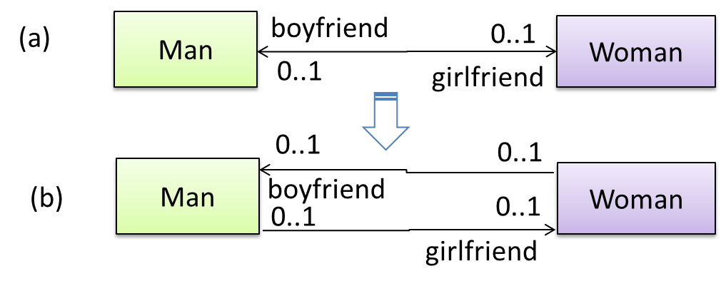
A bidirectional association in the design (shown in (a)) is usually emulated at code level using two variables (as shown in (b)).
class Man {
    Woman girlfriend;

    void setGirlfriend(Woman w) {
        girlfriend = w;
    }
    …
}
class Woman {
    Man boyfriend;

    void setBoyfriend(Man m) {
        boyfriend = m;
    }
}
The two classes are meant to be used as follows:
Woman jean;
Man james;
…
james.setGirlfriend(jean);
jean.setBoyfriend(james);
Suppose the two classes were used this instead:
Woman jean; Man james, yong;
…
james.setGirlfriend(jean);
jean.setBoyfriend(yong);
Now James' girlfriend is Jean, while Jean's boyfriend is not James. This situation results as the code was not defensive enough to stop this "love triangle". In such a situation, we say that the referential integrity has been violated. It simply means there is an inconsistency in object references.

One way to prevent this situation is to implement the two classes as shown below. Note how the referential integrity is maintained.
public class Woman {
    private Man boyfriend;

    public void setBoyfriend(Man m) {
        if(boyfriend == m){
            return;
        }
        if (boyfriend != null) {
            boyfriend.breakUp();
        }
        boyfriend = m;
        m.setGirlfriend(this);
    }

    public void breakUp() {
        boyfriend = null;
    }
    ...
}
public class Man{
    private Woman girlfriend;

    public void setGirlfriend(Woman w) {
        if(girlfriend == w){
            return;
        }
        if (girlfriend != null) {
            girlfriend.breakUp();
        }
        girlfriend = w;
        w.setBoyfriend(this);
    }
    public void breakUp() {
        girlfriend = null;
    }
   ...
}
When the code james.setGirlfriend(jean) is executed, the code ensures that james break up with any current girlfriend before he accepts jean as the girlfriend. Furthermore, the code ensures
that jean breaks up with any existing boyfriends and accepts james as the boyfriend.
Imagine that we now support the following feature in our Minesweeper game.
Feature ID: multiplayer
Description: A minefield is divided into mine regions. Each region is assigned to a single player. Players can swap regions. To win the game, all regions must be cleared.
Given below is an extract from our class diagram.
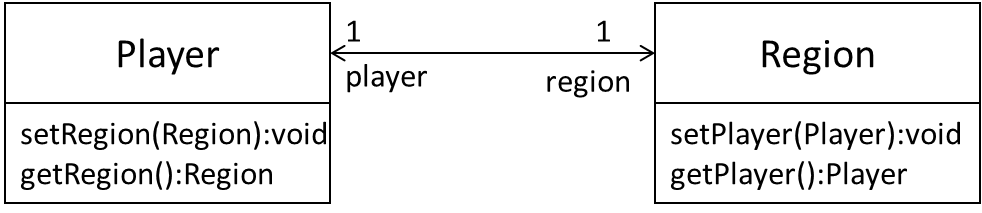
Minimally, this can be implemented like this.
class Player{
    Region region;
    void setRegion(Region r) {
        region = r;
    }
    Region getRegion() {
        return region;
    }
}

// Region class is similar
However, this is not very defensive. For example, a user of this class can pass a null to either of the methods, thus violating the multiplicity of the relationship.
Implement the two classes using a more defensive approach. Take note of the bidirectional link which requires us to preserve referential integrity at all times.
In this solution, we assume Regions can be created without Players (note that we cannot be 100% defensive all the time). The usage will be something like this:
Region r1 = new Region();
Player p1 = new Player(r1);
Region r2 = new Region();
Player p2 = new Player(r2);
p1.setRegion(r2);
r1.setPlayer(p2);
Here are the two classes. Get methods are omitted as they are simple. Note how much extra effort we need to be defensive.
public class Region {
    private Player myPlayer;

    public Region() {
        // initialise region
    }

    public void setPlayer(Player newPlayer) {
        if (newPlayer == null) {
            stopSystemWithErrorMessage("Multiplicity violation");
        }
        if (myPlayer == newPlayer) {
            return; // same player
        }
        if (myPlayer != null) {
            // I already have a Player!
            myPlayer.removeRegion(this);
        }
        myPlayer = newPlayer;
        // set the reverse link
        myPlayer.setRegion(this);
    }

    public void removePlayer(Player disconnectingPlayer) {
        if (myPlayer == disconnectingPlayer){
            myPlayer = null;
        } else {
            stopSystemWithErrorMessage("Unknown Player trying to disconnect");
        }
    }

    private void stopSystemWithErrorMessage(String msg) {
        ...
    }
}
public class Player {
    private Region myRegion;

    public Player(Region region) {
        setRegion(region);
    }

    public void setRegion(Region newRegion) {
        if (newRegion == null) {
            stopSystemWithErrorMessage("Multiplicity violation");
        }
        if (myRegion == newRegion) {
            return; // no change in Region!
        }
        if (myRegion != null) {
            // previous region exists
            myRegion.removePlayer(this);
        }
        myRegion = newRegion;

        // set the reverse link
        myRegion.setPlayer(this);
    }

    public void removeRegion(Region disconnectingRegion) {
        if (myRegion == disconnectingRegion) {
            myRegion = null;
        }
    }

    private void stopSystemWithErrorMessage(String msg) {
        ...
    }
}
Note that the above code stops the system when the multiplicity is violated. Alternatively, we can throw an exception and let the caller handle the situation.
Implement this bidirectional association. Note that the Bank uses accNumber attribute to uniquely identify an Account object. Assume the Bank class is responsible for
maintaining the links between objects.
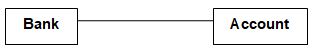
The code below contains a method in the Bank class to create an account; the bank field in the new account is thereby filled by the bank creating it.
We assume that once an Account has been assigned to one Bank, it cannot be assigned to a different Bank. Once the Account is removed from the Bank, it
will not be used any more (hence, no need to remove the link from Account to Bank).
public class Account {
    private int accNumber ;
    private Bank theBank ;

    public Account(int n, Bank b) {
        accno = n ;
        theBank = b ;
    }
    public int getNumber() {
        return accNumber;
    }
    public Bank getBank() {
        return theBank ;
    }
}
import java.util.*;

public class Bank {
    private HashMap< Integer, Account > theAccounts = new HashMap < Integer, Account > ();

    public void createAccount(int n) {
        addAccount(new Account(n, this)) ;
    }
    public void addAccount(Account a) {
        theAccounts.put(a.getNumber(), a);
    }
    public void removeAccount(int accNumber) {
        theAccounts.remove(accNumber);
    }
    public Account lookupAccount(int accNumber) {
        return theAccounts.get(accNumber);
    }
}
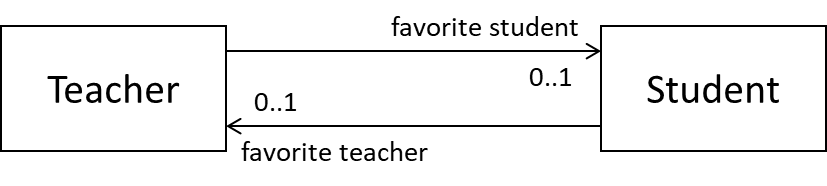
(a) Is the code given below a defensive translation of the associations shown in the class diagram? Explain your answer.
class Teacher{
    private Student favoriteStudent;

    void setFavoriteStudent(Student s){
        favoriteStudent = s;
    }
}
class Student{
    private Teacher favoriteTeacher;

    void setFavoriteTeacher(Teacher t){
        favoriteTeacher = t;
    }
}
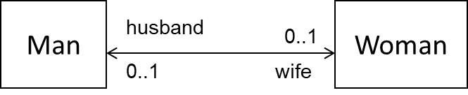
(b) In terms of maintaining referential integrity in the implementation, what is the difference between the following two diagrams?
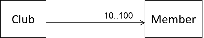
(c) Show a defensive implementation of the remove(Member m) of the Club class given below.
(a) Yes. Each links is mutable and unidirectional. A simple reference variable is suitable to hold the link.
Teacher class can be made even more defensive by introducing a resetFavoriteStudent() method to unlink the current favorite student from a teacher. In that case, setFavoriteStudent(Student) method should not accept null. This approach is more defensive because it prevents a null value being passed to setFavoriteStudent(Student) by mistake and being interpreted as a request to de-link the
current favorite student from the Teacher object.
(b) First diagram has unidirectional links. Second has a bidirectional link. RI is only applicable to the second.
(c)
void removeMember(Member m) {
    if (m==null) {
        throw exception("this is null, not a member!");
    } else if(member_count == 10) {
        throw exception("we need at least 10 members to survive!");
    } else if(!isMember(m)) {
        throw exception ("this fellow is not a member of our club!");
    } else {
        members.remove(m); // members is a data structure such as ArrayList
    }
}
Bidirectional associations, if not implemented properly, can result in referential integrity violations.
True
Explanation: Bidirectional associations require two objects to link to each other. When one of these links is not consistent with the other, we have a referential integrity violation.
W9.4e Can explain when to use defensive programming
Implementation → Error Handling → Defensive Programming →
When
It is not necessary to be 100% defensive all the time. While defensive code may be less prone to be misused or abused, such code can also be more complicated and slower to run.
The suitable degree of defensiveness depends on many factors such as:
- How critical is the system?
- Will the code be used by programmers other than the author?
- The level of programming language support for defensive programming
- The overhead of being defensive
Defensive programming,
- a. can make the program slower.
- b. can make the code longer.
- c. can make the code more complex.
- d. can make the code less susceptible to misuse.
- e. can require extra effort.
(a)(b)(c)(d)(e)
Explanation: Defensive programming requires a more checks, possibly making the code longer, more complex, and possibly slower. Use it only when benefits outweigh costs, which is often.
W9.4f Can explain the Design-by-Contract approach
Implementation → Error Handling → Design by Contract →
Design by Contract
Suppose an operation is implemented with the behavior specified precisely in the API (preconditions, post conditions, exceptions etc.). When following the defensive approach, the code should first check if the preconditions have been met. Typically, exceptions are thrown if preconditions are violated. In contrast, the Design-by-Contract (DbC) approach to coding assumes that it is the responsibility of the caller to ensure all preconditions are met. The operation will honor the contract only if the preconditions have been met. If any of them have not been met, the behavior of the operation is "unspecified".
Languages such as Eiffel have native support for DbC. For example, preconditions of an operation can be specified in Eiffel and the language runtime will check precondition violations without the need to do it explicitly in the code. To follow the DbC approach in languages such as Java and C++ where there is no built-in DbC support, assertions can be used to confirm pre-conditions.
Which statements are correct?
- a. It is not natively supported by Java and C++.
- b. It is an alternative to OOP.
- c. It assumes the caller of a method is responsible for ensuring all preconditions are met.
(a)(b)(c)
Explanation: DbC is not an alternative to OOP. We can use DbC in an OOP solution.
Quality Assurance
W9.5 Can use intermediate-level testing techniques
W9.5a Can explain testability
Quality Assurance → Testing → Introduction →
Testability
Testability is an indication of how easy it is to test an SUT. As testability depends a lot on the design and implementation. You should try to increase the testability when you design and implement a software. The higher the testability, the easier it is to achieve a better quality software.
W9.5b Can explain test coverage
Quality Assurance → Testing → Test Coverage →
What
Test coverage is a metric used to measure the extent to which testing exercises the code i.e., how much of the code is 'covered' by the tests.
Here are some examples of different coverage criteria:
- Function/method coverage : based on functions executed e.g., testing executed 90 out of 100 functions.
- Statement coverage : based on the number of line of code executed e.g., testing executed 23k out of 25k LOC.
- Decision/branch coverage : based on the decision points exercised e.g., an
ifstatement evaluated to bothtrueandfalsewith separate test cases during testing is considered 'covered'. - Condition coverage : based on the boolean sub-expressions, each evaluated to both true and false with different test cases. Condition coverage is not the same as the decision coverage.
if(x > 2 && x < 44) is considered one decision point but two conditions.
For 100% branch or decision coverage, two test cases are required:
(x > 2 && x < 44) == true: [e.g.x == 4](x > 2 && x < 44) == false: [e.g.x == 100]
For 100% condition coverage, three test cases are required
(x > 2) == true,(x < 44) == true: [e.g.x == 4](x < 44) == false: [e.g.x == 100](x > 2) == false: [e.g.x == 0]
- Path coverage measures coverage in terms of possible paths through a given part of the code executed. 100% path coverage means all possible paths have been executed. A commonly used notation for path analysis is called the Control Flow Graph (CFG).
- Entry/exit coverage measures coverage in terms of possible calls to and exits from the operations in the SUT.
Which of these gives us the highest intensity of testing?
(b)
Explanation: 100% path coverage implies all possible execution paths through the SUT have been tested. This is essentially ‘exhaustive testing’. While this is very hard to achieve for a non-trivial SUT, it technically gives us the highest intensity of testing. If all tests pass at 100% path coverage, the SUT code can be considered ‘bug free’. However, note that path coverage does not include paths that are missing from the code altogether because the programmer left them out by mistake.
Evidence:
Explain what is test coverage and how it can be useful.
W9.5c Can explain how test coverage works
Quality Assurance → Testing → Test Coverage →
How
Measuring coverage is often done using coverage analysis tools. Most IDEs have inbuilt support for measuring test coverage, or at least have plugins that can measure test coverage.
Coverage analysis can be useful in improving the quality of testing e.g., if a set of test cases does not achieve 100% branch coverage, more test cases can be added to cover missed branches.
Measuring code coverage in Intellij IDEA
Evidence:
Measure test coverage in your project.
W9.5d Can use intermediate features of JUnit
Tools → JUnit →
JUnit: Intermediate
Some intermediate JUnit techniques that may be useful:
- It is possible for a JUnit test case to verify if the SUT throws the right exception.
- JUnit Rules are a way to add additional behavior to a test. e.g. to make a test case use a temporary folder for storing files needed for (or generated by) the test.
- It is possible to write methods thar are automatically run before/after a test method/class. These are useful to do pre/post cleanups for example.
- Testing private methods is possible, although not always necessray
Evidence:
Use the mentioned features in the project.
W9.5e Can explain TDD
Quality Assurance → Testing → Test-Driven Development →
What
Test-Driven Development(TDD)_ advocates writing the tests before writing the SUT, while evolving functionality and tests in small increments. In TDD you first define the precise behavior of the SUT using test cases, and then write the SUT to match the specified behavior. While TDD has its fair share of detractors, there are many who consider it a good way to reduce defects. One big advantage of TDD is that it guarantees the code is testable.
A) In TDD, we write all the test cases before we start writing functional code.
B) Testing tools such as Junit require us to follow TDD.
A) False
Explanation: No, not all. We proceed in small steps, writing tests and functional code in tandem, but writing the test before we write the corresponding functional code.
B) False
Explanation: They can be used for TDD, but they can be used without TDD too.
W9.6 Can explain some QA techniques complementary to testing
W9.6a Can explain software quality assurance
Quality Assurance → Quality Assurance → Introduction →
What
Software Quality Assurance (QA) is the process of ensuring that the software being built has the required levels of quality.
While testing is the most common activity used in QA, there are other complementary techniques such as static analysis, code reviews, and formal verification.
W9.6b Can explain validation and verification
Quality Assurance → Quality Assurance → Introduction →
Validation vs Verification
Quality Assurance = Validation + Verification
QA involves checking two aspects:
- Validation: are we building the right system i.e., are the requirements correct?
- Verification: are we building the system right i.e., are the requirements implemented correctly?
Whether something belongs under validation or verification is not that important. What is more important is both are done, instead of limiting to verification (i.e., remember that the requirements can be wrong too).
Choose the correct statements about validation and verification.
- a. Validation: Are we building the right product?, Verification: Are we building the product right?
- b. It is very important to clearly distinguish between validation and verification.
- c. The important thing about validation and verification is to remember to pay adequate attention to both.
- d. Developer-testing is more about verification than validation.
- e. QA covers both validation and verification.
- f. A system crash is more likely to be a verification failure than a validation failure.
(a)(b)(c)(d)(e)(f)
Explanation:
Whether something belongs under validation or verification is not that important. What is more important is that we do both.
Developer testing is more about bugs in code, rather than bugs in the requirements.
In QA, system testing is more about verification (does the system follow the specification?) and acceptance testings is more about validation (does the system solve the user’s problem?).
A system crash is more likely to be a bug in the code, not in the requirements.
Evidence:
Explain validations and verification with concrete examples from the project.
W9.6c Can explain code reviews
Quality Assurance → Quality Assurance → Code Reviews →
What
Code review is the systematic examination code with the intention of finding where the code can be improved.
Reviews can be done in various forms. Some examples below:
-
In
pair programming - As pair programming involves two programmers working on the same code at the same time, there is an implicit review of the code by the other member of the pair.
Pair Programming:
Pair programming is an agile software development technique in which two programmers work together at one workstation. One, the driver, writes code while the other, the observer or navigator, reviews each line of code as it is typed in. The two programmers switch roles frequently. [source: Wikipedia]

A good introduction to pair programming:
-
Pull Request reviews
- Project Management Platforms such as GitHub and BitBucket allows the new code to be proposed as Pull Requests and provides the ability for others to review the code in the PR.
-
Formal inspections
-
Inspections involve a group of people systematically examining a project artifacts to discover defects. Members of the inspection team play various roles during the process, such as:
- the author - the creator of the artifact
- the moderator - the planner and executor of the inspection meeting
- the secretary - the recorder of the findings of the inspection
- the inspector/reviewer - the one who inspects/reviews the artifact.
-
Advantages of code reviews over testing:
- It can detect functionality defects as well as other problems such as coding standard violations.
- Can verify non-code artifacts and incomplete code
- Do not require test drivers or stubs.
Disadvantages:
- It is a manual process and therefore, error prone.
Evidence:
Review PRs in the project.
W9.6d Can explain static analysis
Quality Assurance → Quality Assurance → Static Analysis →
What
Static analysis: Static analysis is the analysis of code without actually executing the code.
Static analysis of code can find useful information such unused variables, unhandled exceptions, style errors, and statistics. Most modern IDEs come with some inbuilt static analysis capabilities. For example, an IDE can highlight unused variables as you type the code into the editor.
Higher-end static analyzer tools can perform for more complex analysis such as locating potential bugs, memory leaks, inefficient code structures etc.
Some example static analyzer for Java:
Linters are a subset of static analyzers that specifically aim to locate areas where the code can be made 'cleaner'.
Evidence:
Explain how static analysis is used in the project.
W9.6e Can explain formal verification
Quality Assurance → Quality Assurance → Formal Verification →
What
Formal verification uses mathematical techniques to prove the correctness of a program.
by Eric Hehner
Advantages:
- Formal verification can be used to prove the absence of errors. In contrast, testing can only prove the presence of error, not their absence.
Disadvantages:
- It only proves the compliance with the specification, but not the actual utility of the software.
- It requires highly specialized notations and knowledge which makes it an expensive technique to administer. Therefore, formal verifications are more commonly used in safety-critical software such as flight control systems.
Testing cannot prove the absence of errors. It can only prove the presence of errors. However, formal methods can prove the absence of errors.
True
Explanation: While using formal methods is more expensive than testing, it indeed can prove the correctness of a piece of software conclusively, in certain contexts. Getting such proof via testing requires exhaustive testing, which is not practical to do in most cases.
Documentation
W9.7 Can apply best practices when writing developer documents
Type of Developer Docs
W9.7a Can explain the two types of developer docs
Implementation → Documentation → Introduction →
What
Developer-to-developer documentation can be in one of two forms:
- Documentation for developer-as-user: Software components are written by developers and reused by other developers, which means there is a need to document how such components are to be used. Such documentation
can take several forms:
- API documentation: APIs expose functionality in small-sized, independent and easy-to-use chunks, each of which can be documented systematically.
- Tutorial-style instructional documentation: In addition to explaining functions/methods independently, some higher-level explanations of how to use an API can be useful.
- Example of API Documentation: String API.
- Example of tutorial-style documentation: Java Intenatioanalization Tutorial
- Example of API Documentation: string API.
- Example of tutorial-style documentation: How to use Regular Expressions in Python
- Documentation for developer-as-maintainer: There is a need to document how a system or a component is designed, implemented and tested so that other developers can maintain and evolve the code. Writing documentation of this type is harder because of the need to explain complex internal details. However, given that readers of this type of documentation usually have access to the source code itself, only some information need to be included in the documentation, as code (and code comments) can also serve as a complementary source of information.
- An example: se-edu/addressbook-level4 Developer Guide.
Choose correct statements about API documentation.
- a. They are useful for both developers who use the API and developers who maintain the API implementation.
- b. There are tools that can generate API documents from code comments.
- d. API documentation may contain code examples.
All
Evidence:
Give examples of the two types of developer documents from the project.
Guideline: Aim for Comprehensibility
W9.7b Can explain the need for comprehensibility in documents
Implementation → Documentation → Guidelines → Aim for Comprehensibility →
What
Technical documents exist to help others understand technical details. Therefore, it is not enough for the documentation to be accurate and comprehensive, it should also be comprehensible too.
W9.7c Can write reasonably comprehensible developer documents
Implementation → Documentation → Guidelines → Aim for Comprehensibility →
How
Here are some tips on writing effective documentation.
- Use plenty of diagrams: It is not enough to explain something in words; complement it with visual illustrations (e.g. a UML diagram).
- Use plenty of examples: When explaining algorithms, show a running example to illustrate each step of the algorithm, in parallel to worded explanations.
- Use simple and direct explanations: Convoluted explanations and fancy words will annoy readers. Avoid long sentences.
- Get rid of statements that do not add value: For example, 'We made sure our system works perfectly' (who didn't?), 'Component X has its own responsibilities' (of course it has!).
- It is not a good idea to have separate sections for each type of artifact, such as 'use cases', 'sequence diagrams', 'activity diagrams', etc. Such a structure, coupled with the indiscriminate inclusion of diagrams without justifying their need, indicates a failure to understand the purpose of documentation. Include diagrams when they are needed to explain something. If you want to provide additional diagrams for completeness' sake, include them in the appendix as a reference.
It is recommended for developer documents,
- a. to have separate sections for each type of diagrams such as class diagrams, sequence diagrams, use case diagrams etc.
- b. to give a high priority to comprehension too, not stop at comprehensiveness only.
(a)(b)
Explanation:
(a) Use diagrams when they help to understand the text descriptions. Text and diagrams should be used in tandem. Having separate sections for each diagram type is a sign of generating diagrams for the sake of having them.
(b) Both are important, but lengthy, complete, accurate yet hard to understand documents are not that useful.
Evidence:
Follow the guideline when documenting the project.
Guideline: Describe Top-Down
W9.7d Can distinguish between top-down and bottom up documentation
Implementation → Documentation → Guidelines → Describe Top-Down →
What
When writing project documents, a top-down breadth-first explanation is easier to understand than a bottom-up one.
W9.7e Can explain the advantages of top-down documentation
Implementation → Documentation → Guidelines → Describe Top-Down →
Why
The main advantage of the top-down approach is that the document is structured like an upside down tree (root at the top) and the reader can travel down a path she is interested in until she reaches the component she is interested to learn in-depth, without having to read the entire document or understand the whole system.
Evidence:
Explain advantages of top-down documents by using the project's Developer Guide as an example.
W9.7f Can write documentation in a top-down manner
Implementation → Documentation → Guidelines → Describe Top-Down →
How
To explain a system called SystemFoo with two sub-systems, FrontEnd and BackEnd, start by describing the system at the highest level of abstraction, and progressively
drill down to lower level details. An outline for such a description is given below.
[First, explain what the system is, in a black-box fashion (no internal details, only the external view).]
SystemFoois a ....
[Next, explain the high-level architecture of SystemFoo, referring to its major components only.]
SystemFooconsists of two major components:FrontEndandBackEnd.
The job ofFrontEndis to ... while the job ofBackEndis to ...
And this is howFrontEndandBackEndwork together ...
[Now we can drill down to FrontEnd's details.]
FrontEndconsists of three major components:A,B,C
A's job is to ...B's job is to...C's job is to...
And this is how the three components work together ...
[At this point, further drill down the internal workings of each component. A reader who is not interested in knowing nitty-gritty details can skip ahead to the section on BackEnd.]
In-depth description of
A
In-depth description ofB
...
[At this point drill down details of the BackEnd.]
...
Evidence:
Follow the guideline when documenting the project.
Guideline: Minimal but Sufficient
W9.7g Can explain documentation should be minimal yet sufficient
Implementation → Documentation → Guidelines → Minimal but Sufficient →
What
Aim for 'just enough' developer documentation.
- Writing and maintaining developer documents is an overhead. You should try to minimize that overhead.
- If the readers are developers who will eventually read the code, the documentation should complement the code and should provide only just enough guidance to get started.
W9.7h Can write minimal yet sufficient documentation
Implementation → Documentation → Guidelines → Minimal but Sufficient →
How
Anything that is already clear in the code need not be described in words. Instead, focus on providing higher level information that is not readily visible in the code or comments.
Refrain from duplicating chunks or text. When describing several similar algorithms/designs/APIs, etc., do not simply duplicate large chunks of text. Instead, describe the similarity in one place and emphasize only the differences in other places. It is very annoying to see pages and pages of similar text without any indication as to how they differ from each other.
Drawing Architecture Diagrams
W9.7i Can draw an architecture diagram
Design → Architecture → Architecture Diagrams →
Drawing
While architecture diagrams have no standard notation, try to follow these basic guidelines when drawing them.
-
Minimize the variety of symbols. If the symbols you choose do not have widely-understood meanings e.g. A drum symbol is widely-understood as representing a database, explain their meaning.
-
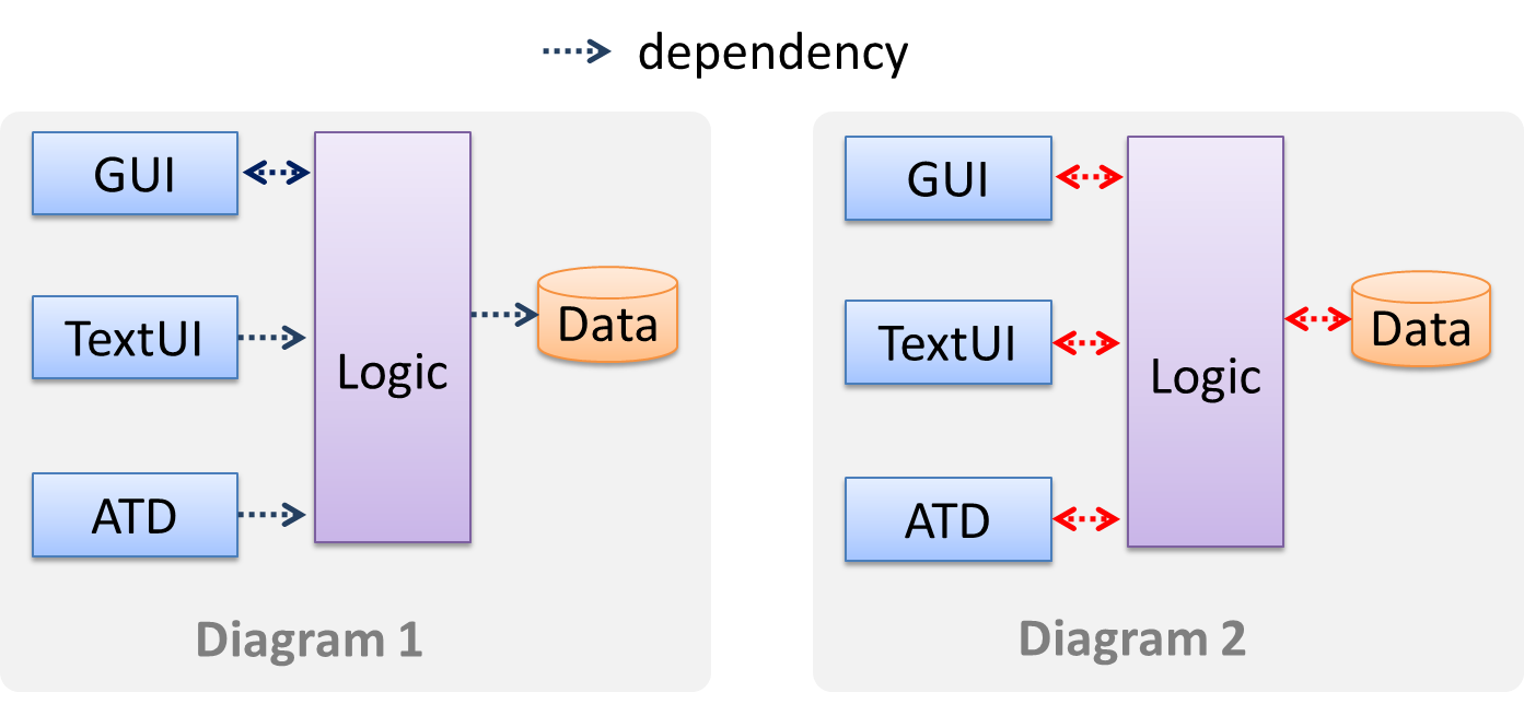
Avoid the indiscriminate use of double-headed arrows to show interactions between components.
Consider the two architecture diagrams of the same software given below. Because Diagram 2 uses double headed arrows, the important fact that GUI has a bi-directional dependency with
the Logic component is no longer captured.
🅿️ Project
W9.8 Can write developer documentation
Covered by:
Tutorial 9
Show evidence of achieving v1.2 team/individual milestone
- [One member] Show the 'insights' tab of your team repo's GitHub page
- [Each member] show these using the
masterbranch in your computer:- Demo the enhancement you added to v1.2
- Point out the part you added to the Developer Guide
Questions to be discussed during tutorial
- Can an object of
Bbe substituted for an object ofA?
class A {
    void foo() {
        System.out.println("Foo from A");
    }
}

class B extends A {
    void foo() throws IOException {
        System.out.println("Foo from B");
    }
}
- Which method is statically bound which method is dynamically bound?
class Animal {
    // 1
    void eat() {
        System.out.println("Eat food");
    }
}

class Dog extends Animal {
    // 2
    void eat() {
        System.out.println("Eat dog food");
    }
    // 3
    void eat(String b) {
        System.out.println("Eat biscuit: " + b);
    }
}
- Consider the diagram:
Which is a better design? - In the above figure, what is the problem with the diagram on the right?
- IVLE quizzes allow a quiz to be attempted multiple times by students. For each attempt, it records the time taken. Model this scenario as a class diagram.
- Draw another diagram to describe how you would implement the above it in code.
- Give an example of defensive programming from AB4
- What is the purpose of
@Beforeand@Afterin JUnit? - What is the difference between decision and condition coverage?
- Acceptance tests are validation tests, why?
W9.1b Can use simple class diagrams and sequence
diagrams to model an OO solution
Design → Modeling → Modeling a Solution →
Basic
As mentioned in [
Design → Modeling → Modeling a Solution →
Introduction
You can use models to analyze and design a software before you start coding.
Suppose You are planning to implement a simple minesweeper game that has a text based UI and a GUI. Given below is a possible OOP design for the game.
Before jumping into coding, you may want to find out things such as,
- Is this class structure is able to produce the behavior we want?
- What API should each class have?
- Do we need more classes?
To answer those questions, you can analyze the how the objects of these classes will interact with each other to produce the behavior you want.
Let us start by modelling a sample interaction between the person playing the game and the TextUi object.
newgame and clear x y represent commands typed by the Player on the TextUi.
How does the TextUi object carry out the requests it has received from player? It would need to interact with other objects of the system. Because the Logic class is the one that controls the game logic,
the TextUi needs to collaborate with Logic to fulfill the newgame request. Let us extend the model to capture that interaction.
W = Width of the minefield; H = Height of the minefield
The above diagram assumes that W and H are the only information TextUi requires to display the minefield to the Player. Note that there could be other ways of doing this.
The Logic methods we conceptualized in our modelling so far are:
Now, let us look at what other objects and interactions are needed to support the newGame() operation. It is likely that a new Minefield object is created when the newGame() method is called.
Note that the behavior of the Minefield constructor has been abstracted away. It can be designed at a later stage.
Given below are the interactions between the player and the Text UI for the whole game.
💡 Note that
Defining the architecture-level APIs for a small Tic-Tac-Toe game:
Evidence:
Use models to design/document future features of your project.
W9.1c Can use intermediate class diagram and sequence
diagram concepts to model an OO design
Design → Modeling → Modeling a Solution →
Intermediate
Continuing with the example in [
Design → Modeling → Modeling a Solution →
Basic
As mentioned in [
Design → Modeling → Modeling a Solution →
Introduction
You can use models to analyze and design a software before you start coding.
Suppose You are planning to implement a simple minesweeper game that has a text based UI and a GUI. Given below is a possible OOP design for the game.
Before jumping into coding, you may want to find out things such as,
- Is this class structure is able to produce the behavior we want?
- What API should each class have?
- Do we need more classes?
To answer those questions, you can analyze the how the objects of these classes will interact with each other to produce the behavior you want.
Let us start by modelling a sample interaction between the person playing the game and the TextUi object.
newgame and clear x y represent commands typed by the Player on the TextUi.
How does the TextUi object carry out the requests it has received from player? It would need to interact with other objects of the system. Because the Logic class is the one that controls the
game logic, the TextUi needs to collaborate with Logic to fulfill the newgame request. Let us extend the model to capture that interaction.
W = Width of the minefield; H = Height of the minefield
The above diagram assumes that W and H are the only information TextUi requires to display the minefield to the Player. Note that there could be other ways of doing
this.
The Logic methods we conceptualized in our modelling so far are:
Now, let us look at what other objects and interactions are needed to support the newGame() operation. It is likely that a new Minefield object is created when the newGame() method
is called.
Note that the behavior of the Minefield constructor has been abstracted away. It can be designed at a later stage.
Given below are the interactions between the player and the Text UI for the whole game.
💡 Note that
Defining the architecture-level APIs for a small Tic-Tac-Toe game:
This interaction adds the following methods to the Logic class
clearCellAt(int x, int y)markCellAt(int x, int y)getGameState() :GAME_STATE (GAME_STATE: READY, IN_PLAY, WON, LOST, …)
And it adds the following operation to Logic API:
getAppearanceOfCellAt(int,int):CELL_APPEARANCE (CELL_APPEARANCE: HIDDEN, ZERO, ONE, TWO, THREE, …, MARKED, INCORRECTLY_MARKED, INCORRECTLY_CLEARED)
In the above design, TextUi does not access Cell objects directly. Instead, it gets values of type CELL_APPEARANCE from Logic to be displayed as a minefield to the player. Alternatively,
each cell or the entire Minefield can be passed directly to TextUi.
Here is the updated class diagram:
The above is for the case when Actor Player interacts with the system using a text UI. Additional operations (if any) required for the GUI can be discovered similarly. Suppose Logic supports a reset() operation. We can model it like this:
Our current model assumes that the Minefield object has enough information (i.e. H, W, and mine locations) to create itself.
An alternative is to have a ConfigGenerator object that generates a string containing the minefield information as shown below.
In addition, getWidth(), getHeight(), markCellAt(x,y) and clearCellAt(x,y) can be handled like this.
The updated class diagram:
How is getGameState() operation supported? Given below are two ways (there could be other ways):
Minefieldclass knows the state of the game at any time.Logicclass retrieves it from theMinefieldclass as and when required.Logicclass maintains the state of the game at all times.
Here’s the SD for option 1.
Here’s the SD for option 2. Here, assume that the game state is updated after every mark/clear action.
It is now time to explore what happens inside the Minefield constructor? One way is to design it as follows.
Now let us assume that Minesweeper supports a ‘timing’ feature.
Updated class diagram:
💡 When designing components, it is not necessary to draw elaborate UML diagrams capturing all details of the design. They can be done as rough sketches. For example, draw sequence diagrams only when you are not sure which operations are required by each class, or when you want to verify that your class structure can indeed support the required operations.
Evidence:
Use models to design/document future features of your project.
W9.2c Can explain how substitutability operation
overriding, and dynamic binding relates to polymorphism
Paradigms → Object Oriented Programming → Polymorphism →
How
Three concepts combine to achieve polymorphism: substitutability, operation overriding, and dynamic binding.
- Substitutability: Because of substitutability, you can write code that expects object of a parent class and yet use that code with objects of child classes. That is how polymorphism is able to treat objects of different types as one type.
- Overriding: To get polymorphic behavior from an operation, the operation in the superclass needs to be overridden in each of the subclasses. That is how overriding allows objects of different subclasses to display different behaviors in response to the same method call.
- Dynamic binding: Calls to overridden methods are bound to the implementation of the actual object's class dynamically during the runtime. That is how the polymorphic code can call the method of the parent class and yet execute the implementation of the child class.
Which one of these is least related to how OO programs achieve polymorphism?
(c)
Explanation: Operation overriding is the one that is related, not operation overloading.
Evidence:
Explain how substitutability operation overriding, and dynamic binding relates to polymorphism by taking a real example from the project.
W9.2f Can explain Liskov Substitution Principle
Supplmentary → Principles →
Liskov Substitution Principle
Liskov Substitution Principle (LSP): Derived classes must be substitutable for their base classes. -- proposed by Barbara Liskov
LSP sounds same as
Paradigms → Object Oriented Programming → Inheritance →
Substitutability
Every instance of a subclass is an instance of the superclass, but not vice-versa. As a result, inheritance allows substitutability : the ability to substitute a child class object where a parent class object is expected.
an Academic is an instance of a Staff, but a Staff is not necessarily an instance of an Academic. i.e. wherever an object of the
superclass is expected, it can be substituted by an object of any of its subclasses.
The following code is valid because an AcademicStaff object is substitutable as a Staff object.
Staff staff = new AcademicStaff (); // OK
But the following code is not valid because staff is declared as a Staff type and therefore its value may or may not be of type AcademicStaff, which is the type expected by variable academicStaff.
Staff staff;
...
AcademicStaff academicStaff = staff; // Not OK
Suppose the Payroll class depends on the adjustMySalary(int percent) method of the Staff class. Furthermore, the Staff class states that the
adjustMySalary method will work for all positive percent values. Both Admin and Academic classes override the adjustMySalary method.
Now consider the following:
Admin#adjustMySalarymethod works for both negative and positive percent values.Academic#adjustMySalarymethod works for percent values1..100only.
In the above scenario,
Adminclass follows LSP because it fulfillsPayroll’s expectation ofStaffobjects (i.e. it works for all positive values). SubstitutingAdminobjects for Staff objects will not break thePayrollclass functionality.Academicclass violates LSP because it will not work for percent values over100as expected by thePayrollclass. SubstitutingAcademicobjects forStaffobjects can potentially break thePayrollclass functionality.
The Rectangle#resize() can take any integers for height and width. This contract is violated by the subclass Square#resize() because it does
not accept a height that is different from the width.
class Rectangle {
    ...
    /** sets the size to given height and width*/
    void resize(int height, int width){
        ...
    }
}


class Square extends Rectangle {

    @Override
    void resize(int height, int width){
        if (height != width) {
            //error
       }
    }
}
Now consider the following method that is written to work with the Rectangle class.
void makeSameSize(Rectangle original, Rectangle toResize){
    toResize.resize(original.getHeight(), original.getWidth());
}
This code will fail if it is called as maekSameSize(new Rectangle(12,8), new Square(4, 4)) That is, Square class is not substitutable for the Rectangle class.
If a subclass imposes more restrictive conditions than its parent class, it violates Liskov Substitution Principle.
True.
Explanation: If the subclass is more restrictive than the parent class, code that worked with the parent class may not work with the child class. Hence, the substitutability does not exist and LSP has been violated.
Evidence:
Give an example from the project where LSP is followed. Explain what kind of a change to that code will violate LSP e.g. Here, the superclass X and the subclass Y follow LSP. But if we change X in this way, or Y in this way, it will no longer follow LSP
W9.3a Can explain the meaning of association classes
Paradigms → Object Oriented Programming → Associations →
Association Classes
An association class represents additional information about an association. It is a normal class but plays a special role from a design point of view.
A Man class and a Woman class is linked with a ‘married to’ association and there is a need to store the date of marriage. However, that data is related to the association
rather than specifically owned by either the Man object or the Woman object. In such situations, an additional association class can be introduced, e.g. a Marriage class, to store such
information.
Implementing association classes
There is no special way to implement an association class. It can be implemented as a normal class that has variables to represent the endpoint of the association it represents.
In the code below, the Transaction class is an association class that represent a transaction between a Person who is the seller and another Person who
is the buyer.
class Transaction{

    //all fields are compulsory
    Person seller;
    Person buyer;
    Date date;
    String receiptNumber;

    Marriage (Person seller, Person buyer, Date date, String receiptNumber){
        //set fields
    }
}
Which one of these is the suitable as an Association Class?
- a
- b
- c
- d
(a)(b)(c)(d)
Explanation: Mileage is a property of the car, and not specifically about the association between the Driver and the Car. If Mileage was defined as the total number of miles that car was driven by that driver, then it would be suitable as an association class.
Evidence:
Give more examples of association classes, preferably related to your project.
W9.5b Can explain test coverage
Quality Assurance → Testing → Test Coverage →
What
Test coverage is a metric used to measure the extent to which testing exercises the code i.e., how much of the code is 'covered' by the tests.
Here are some examples of different coverage criteria:
- Function/method coverage : based on functions executed e.g., testing executed 90 out of 100 functions.
- Statement coverage : based on the number of line of code executed e.g., testing executed 23k out of 25k LOC.
- Decision/branch coverage : based on the decision points exercised e.g., an
ifstatement evaluated to bothtrueandfalsewith separate test cases during testing is considered 'covered'. - Condition coverage : based on the boolean sub-expressions, each evaluated to both true and false with different test cases. Condition coverage is not the same as the decision coverage.
if(x > 2 && x < 44) is considered one decision point but two conditions.
For 100% branch or decision coverage, two test cases are required:
(x > 2 && x < 44) == true: [e.g.x == 4](x > 2 && x < 44) == false: [e.g.x == 100]
For 100% condition coverage, three test cases are required
(x > 2) == true,(x < 44) == true: [e.g.x == 4](x < 44) == false: [e.g.x == 100](x > 2) == false: [e.g.x == 0]
- Path coverage measures coverage in terms of possible paths through a given part of the code executed. 100% path coverage means all possible paths have been executed. A commonly used notation for path analysis is called the Control Flow Graph (CFG).
- Entry/exit coverage measures coverage in terms of possible calls to and exits from the operations in the SUT.
Which of these gives us the highest intensity of testing?
(b)
Explanation: 100% path coverage implies all possible execution paths through the SUT have been tested. This is essentially ‘exhaustive testing’. While this is very hard to achieve for a non-trivial SUT, it technically gives us the highest intensity of testing. If all tests pass at 100% path coverage, the SUT code can be considered ‘bug free’. However, note that path coverage does not include paths that are missing from the code altogether because the programmer left them out by mistake.
Evidence:
Explain what is test coverage and how it can be useful.
W9.5c Can explain how test coverage works
Quality Assurance → Testing → Test Coverage →
How
Measuring coverage is often done using coverage analysis tools. Most IDEs have inbuilt support for measuring test coverage, or at least have plugins that can measure test coverage.
Coverage analysis can be useful in improving the quality of testing e.g., if a set of test cases does not achieve 100% branch coverage, more test cases can be added to cover missed branches.
Measuring code coverage in Intellij IDEA
Evidence:
Measure test coverage in your project.
W9.5d Can use intermediate features of JUnit
Tools → JUnit →
JUnit: Intermediate
Some intermediate JUnit techniques that may be useful:
- It is possible for a JUnit test case to verify if the SUT throws the right exception.
- JUnit Rules are a way to add additional behavior to a test. e.g. to make a test case use a temporary folder for storing files needed for (or generated by) the test.
- It is possible to write methods thar are automatically run before/after a test method/class. These are useful to do pre/post cleanups for example.
- Testing private methods is possible, although not always necessray
Evidence:
Use the mentioned features in the project.
W9.6b Can explain validation and verification
Quality Assurance → Quality Assurance → Introduction →
Validation vs Verification
Quality Assurance = Validation + Verification
QA involves checking two aspects:
- Validation: are we building the right system i.e., are the requirements correct?
- Verification: are we building the system right i.e., are the requirements implemented correctly?
Whether something belongs under validation or verification is not that important. What is more important is both are done, instead of limiting to verification (i.e., remember that the requirements can be wrong too).
Choose the correct statements about validation and verification.
- a. Validation: Are we building the right product?, Verification: Are we building the product right?
- b. It is very important to clearly distinguish between validation and verification.
- c. The important thing about validation and verification is to remember to pay adequate attention to both.
- d. Developer-testing is more about verification than validation.
- e. QA covers both validation and verification.
- f. A system crash is more likely to be a verification failure than a validation failure.
(a)(b)(c)(d)(e)(f)
Explanation:
Whether something belongs under validation or verification is not that important. What is more important is that we do both.
Developer testing is more about bugs in code, rather than bugs in the requirements.
In QA, system testing is more about verification (does the system follow the specification?) and acceptance testings is more about validation (does the system solve the user’s problem?).
A system crash is more likely to be a bug in the code, not in the requirements.
Evidence:
Explain validations and verification with concrete examples from the project.
W9.6c Can explain code reviews
Quality Assurance → Quality Assurance → Code Reviews →
What
Code review is the systematic examination code with the intention of finding where the code can be improved.
Reviews can be done in various forms. Some examples below:
-
In
pair programming - As pair programming involves two programmers working on the same code at the same time, there is an implicit review of the code by the other member of the pair.
Pair Programming:
Pair programming is an agile software development technique in which two programmers work together at one workstation. One, the driver, writes code while the other, the observer or navigator, reviews each line of code as it is typed in. The two programmers switch roles frequently. [source: Wikipedia]
A good introduction to pair programming:
-
Pull Request reviews
- Project Management Platforms such as GitHub and BitBucket allows the new code to be proposed as Pull Requests and provides the ability for others to review the code in the PR.
-
Formal inspections
-
Inspections involve a group of people systematically examining a project artifacts to discover defects. Members of the inspection team play various roles during the process, such as:
- the author - the creator of the artifact
- the moderator - the planner and executor of the inspection meeting
- the secretary - the recorder of the findings of the inspection
- the inspector/reviewer - the one who inspects/reviews the artifact.
-
Advantages of code reviews over testing:
- It can detect functionality defects as well as other problems such as coding standard violations.
- Can verify non-code artifacts and incomplete code
- Do not require test drivers or stubs.
Disadvantages:
- It is a manual process and therefore, error prone.
Evidence:
Review PRs in the project.
W9.6d Can explain static analysis
Quality Assurance → Quality Assurance → Static Analysis →
What
Static analysis: Static analysis is the analysis of code without actually executing the code.
Static analysis of code can find useful information such unused variables, unhandled exceptions, style errors, and statistics. Most modern IDEs come with some inbuilt static analysis capabilities. For example, an IDE can highlight unused variables as you type the code into the editor.
Higher-end static analyzer tools can perform for more complex analysis such as locating potential bugs, memory leaks, inefficient code structures etc.
Some example static analyzer for Java:
Linters are a subset of static analyzers that specifically aim to locate areas where the code can be made 'cleaner'.
Evidence:
Explain how static analysis is used in the project.
W9.7a Can explain the two types of developer docs
Implementation → Documentation → Introduction →
What
Developer-to-developer documentation can be in one of two forms:
- Documentation for developer-as-user: Software components are written by developers and reused by other developers, which means there is a need to document how such components are to be used. Such documentation
can take several forms:
- API documentation: APIs expose functionality in small-sized, independent and easy-to-use chunks, each of which can be documented systematically.
- Tutorial-style instructional documentation: In addition to explaining functions/methods independently, some higher-level explanations of how to use an API can be useful.
- Example of API Documentation: String API.
- Example of tutorial-style documentation: Java Intenatioanalization Tutorial
- Example of API Documentation: string API.
- Example of tutorial-style documentation: How to use Regular Expressions in Python
- Documentation for developer-as-maintainer: There is a need to document how a system or a component is designed, implemented and tested so that other developers can maintain and evolve the code. Writing documentation of this type is harder because of the need to explain complex internal details. However, given that readers of this type of documentation usually have access to the source code itself, only some information need to be included in the documentation, as code (and code comments) can also serve as a complementary source of information.
- An example: se-edu/addressbook-level4 Developer Guide.
Choose correct statements about API documentation.
- a. They are useful for both developers who use the API and developers who maintain the API implementation.
- b. There are tools that can generate API documents from code comments.
- d. API documentation may contain code examples.
All
Evidence:
Give examples of the two types of developer documents from the project.
W9.7c Can write reasonably comprehensible developer
documents
Implementation → Documentation → Guidelines → Aim for Comprehensibility →
How
Here are some tips on writing effective documentation.
- Use plenty of diagrams: It is not enough to explain something in words; complement it with visual illustrations (e.g. a UML diagram).
- Use plenty of examples: When explaining algorithms, show a running example to illustrate each step of the algorithm, in parallel to worded explanations.
- Use simple and direct explanations: Convoluted explanations and fancy words will annoy readers. Avoid long sentences.
- Get rid of statements that do not add value: For example, 'We made sure our system works perfectly' (who didn't?), 'Component X has its own responsibilities' (of course it has!).
- It is not a good idea to have separate sections for each type of artifact, such as 'use cases', 'sequence diagrams', 'activity diagrams', etc. Such a structure, coupled with the indiscriminate inclusion of diagrams without justifying their need, indicates a failure to understand the purpose of documentation. Include diagrams when they are needed to explain something. If you want to provide additional diagrams for completeness' sake, include them in the appendix as a reference.
It is recommended for developer documents,
- a. to have separate sections for each type of diagrams such as class diagrams, sequence diagrams, use case diagrams etc.
- b. to give a high priority to comprehension too, not stop at comprehensiveness only.
(a)(b)
Explanation:
(a) Use diagrams when they help to understand the text descriptions. Text and diagrams should be used in tandem. Having separate sections for each diagram type is a sign of generating diagrams for the sake of having them.
(b) Both are important, but lengthy, complete, accurate yet hard to understand documents are not that useful.
Evidence:
Follow the guideline when documenting the project.
W9.7e Can explain the advantages of top-down documentation
Implementation → Documentation → Guidelines → Describe Top-Down →
Why
The main advantage of the top-down approach is that the document is structured like an upside down tree (root at the top) and the reader can travel down a path she is interested in until she reaches the component she is interested to learn in-depth, without having to read the entire document or understand the whole system.
Evidence:
Explain advantages of top-down documents by using the project's Developer Guide as an example.
W9.7f Can write documentation in a top-down manner
Implementation → Documentation → Guidelines → Describe Top-Down →
How
To explain a system called SystemFoo with two sub-systems, FrontEnd and BackEnd, start by describing the system at the highest level of abstraction, and
progressively drill down to lower level details. An outline for such a description is given below.
[First, explain what the system is, in a black-box fashion (no internal details, only the external view).]
SystemFoois a ....
[Next, explain the high-level architecture of SystemFoo, referring to its major components only.]
SystemFooconsists of two major components:FrontEndandBackEnd.
The job ofFrontEndis to ... while the job ofBackEndis to ...
And this is howFrontEndandBackEndwork together ...
[Now we can drill down to FrontEnd's details.]
FrontEndconsists of three major components:A,B,C
A's job is to ...B's job is to...C's job is to...
And this is how the three components work together ...
[At this point, further drill down the internal workings of each component. A reader who is not interested in knowing nitty-gritty details can skip ahead to the section on BackEnd.]
In-depth description of
A
In-depth description ofB
...
[At this point drill down details of the BackEnd.]
...
Evidence:
Follow the guideline when documenting the project.
W9.8 Can write developer documentation
Covered by:
Lecture 9
Slides: Uploaded on IVLE.